We are rightly addicted to energy efficiency but this drug has side effects that have a bearing on the design of both negative and positive pressure flues.
In a positive pressure (PP) flue, exhaust gases are driven by a combination of pressure from fans inside boilers, expansion due to combustion and the buoyancy imparted to them by the residual heat of combustion.
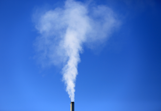
A negative pressure (NP) flue is a heat engine that propels the exhaust upwards using the buoyancy of the residual energy of combustion.
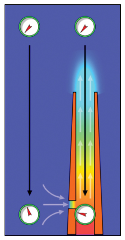
The heat energy in an NP flue has expanded the exhaust with a consequent lowering of its density. This minutely reduces the pressure inside the flue (hence the negative pressure designation) and causes what we perceive as suction at the bottom of the flue where it connects to the boiler. This is commonly known as the draught and the whole is known as the stack effect or natural draught and is measured as pressure differential in Pascals (See Figure 1).
At this point alarm bells should be ringing. The flue is working all the time the boiler is firing so is it taking too much energy? Does it have enough? Has it been designed to work using the least amount of energy for its function? If a chimney is an integral part of a building, does that compromise efficiency?
Boiler manufacturers have worked hard to improve combustion and heat transfer efficiencies with the result that the volume and temperature of exhaust gases have declined. This in turn has reduced the energy available to drive the stack effect.

Figure 1: The stack effect – a negative pressure flue
As a general rule, the greater the height, the greater the draught and the greater the cross-section, the greater the capacity to handle mass-flow. So a tall chimney with a large flue can dispose of the exhaust from a big boiler.
As buoyancy only works upwards, it is important to minimise horizontal runs, which require energy to overcome resistance to flow but achieve no lift. Equally, as the heat energy does the lifting, allowing heat to escape through the flue wall will attenuate the power of the flue to lift the exhaust and so it is essential to insulate the flue adequately. A leaky NP flue will allow ambient air in and this will both collapse the small partial vacuum and lower the heat, which imparts the buoyancy.
Leaks between the inner and outer flues in a concentric air-flue will contaminate the incoming combustion air and attenuate combustion efficiency as the inner, exhaust element of the flue is running at positive pressure and the outer at negative pressure. A combustion gas analyser will reveal this when its exhaust gas probe is applied to the incoming air test port.
So far so simple. Precision in design and adherence to some fundamental rules has become essential. A flue must be straight, vertical, smooth, insulated and the correct height and diameter to lift and disperse the mass-flow from the boiler. These design objectives are achieved by the use of a calculating method which has been refined over more than half a century and was the basis for BS EN 13384:2008. Software employing all the calculations in this standard has proved capable of giving the correct sizing for efficient flues.
Combining this with a designation according to BS EN 1443:2003 will provide the correct characteristics for the given application.
Biomass boilers and gas-fired condensing boilers are good examples of plants that need accurate flue design to support their efficient functioning. Exhaust gas temperatures from condensing boilers of 55°C and below are achieved through precise control over the combustion, the flow of the hot combustion gases and the transfer of heat into the water. There is an internal draught through the combustion chamber or chambers and on through the heat exchanger, and this must not be influenced by the draught in the chimney flue.
High winds cause the draught in the flue to increase through the Bernoulli effect. Fluid passing across an opening drags molecules from the opening, causing molecules farther inside to be drawn up to replace them. Thus, wind lowers pressure at the top of a flue and increases the draught, necessitating the use of draft regulation to prevent the phenomenon from drawing hot combustion gases through the boiler’s heat exchanger faster than the heat can be transferred into the water. Thwarting the boiler designer’s intention in this way causes heat energy to go up the flue instead of meeting the load and wastes fuel.
The use of old flues designed for earlier types of boiler, which created larger volumes of hotter exhaust gases, can cause efficiency loss. An example was found on a north London council estate three years ago. A 26m-high, 55cm-diameter flue, which provided the correct maximum draught for the coal-fired boilers installed in the early 1950s, had been used unconverted through changes from coal to oil to gas to high efficiency (HE) gas.
An irregular, rapid crackling noise which disturbed residents in all eight storeys of flats at the end of the block where the chimney was located was investigated. It was caused by the huge draught necessary to serve 65% efficient coal-fired boilers pulling the flame of the pressure-jet burners in three 0.5MW HE gas boilers off their burner nozzles. This left a gap between the burner nozzle and the rear of the flame occupied by an explosively inflammable mixture of air and gas in the presence of a source of ignition, the flame. Naturally this mixture was repeatedly exploding into flame, being pulled off the nozzle and reigniting. The continual series of explosions was what was irritating the residents.
The draught exceeded that required to serve the gas boilers, and the draught regulators on the primary flues from each of the boilers had been removed to stop the clattering noise they were making as they opened and closed to relieve the excess draught in the flue. With nothing to divert draught from the boiler combustion process it was all going through the boilers.

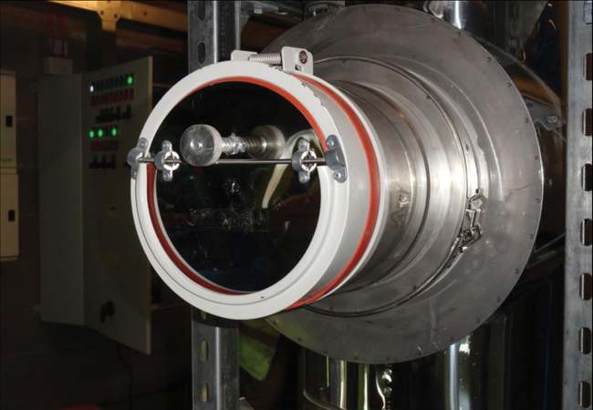
A quiet draught stabiliser
What neither the residents, their tenants’ management office nor the maintenance contractor was aware of, was the fuel this wasted. When this was explained, the flue conversion work was agreed with alacrity. The answer was to reduce the carrying capacity of the flue (equals increasing resistance to flow) by taking its diameter down by 10cm and fitting draught stabilisers with silicone rubber seals to deaden the noise they would make when closing (see image below). The sizing was calculated to allow for poorer flue performance in hot weather, which reduces the temperature differential upon which the stack effect depends. The thermosetting resin liner was installed in two days and is immune to any of the condensates that had progressively damaged the very fine refractory lining installed in the early 50s.
University failure
No liner could save a southern university from an incorrect new flue that had a 19.6m horizontal route including 6 x 45° bends and a 90° bend leading to an 11.5m main riser with its own pair of 45° bends.
That amount of resistance to flow was bound to make the boiler overheat, clinker the ash from its biomass fuel and damage the refractory combustion chamber lining. This led to day-long outages while the clinker was chiselled out by hand and frequent and expensive replacements. The reason – appearances.
The routing of flues in new work needs to be agreed early and determined by engineering principles. If the appearance and position of the chimney is an aesthetic issue then this must be negotiated with the architect on the basis of explanation of the energy efficiency implications of the choices.
Summary
This tells us that improvements in boiler performance must be served by the correctly calculated design of correctly designated flues and that the primary, horizontal flue is there to connect the boiler to the main riser by the shortest route not to hide the chimney from view.
Draught regulators should always be fitted to protect boiler performance from high winds and finally – in the case of the 1950s estate – proves that the updating of old flues is possible and can save the cost of a new chimney.
About the author
Jim Kinnibrugh is a consultant specialising in commercial and industrial chimneys and flue systems. He is the author of chapter 10 of AM15 Biomass Heating and acting chair of the Chimneys and Flues Group


