Controlling the upper and lower limit of temperature in commercial applications, such as in call centres2 and offices3, has been shown to be beneficial to productivity4, as well as – and as a result of – providing a more comfortable environment. The values used for the upper limit for UK offices was recently explored5 and, although there are opportunities for increased temperatures – above current operational norms of, typically, 22°C – it was found that 24°C was the likely acceptable maximum for a conditioned space before there was unacceptable discomfort and a resulting reduction in productivity. So in cases where natural and passive means are not sufficient – or are inappropriate – there are often good reasons to apply active cooling systems.
As post-industrial/commercial buildings are being repurposed to meet the needs of new occupants – often as offices, shops, restaurants and hotels – there is a growing demand for more compact systems. These internal environments are also being designed, as a warmer climate increases cooling needs.6, 7 Building refurbishment activity has been accelerated by the April 2018 deadline in England and Wales that will require commercial properties to have an Energy Performance Certificate (EPC) rating of at least ‘E’. This can be delivered not only by improving the fabric, but also using environmental control systems.

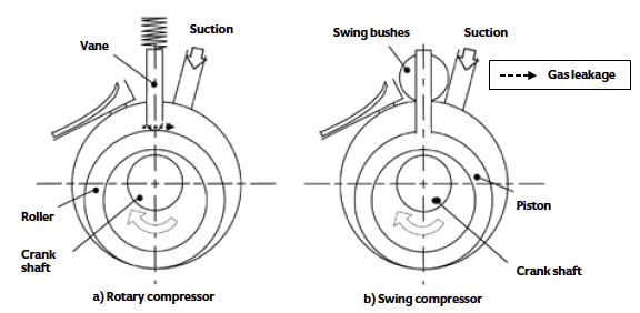
Figure 1: Comparison of a rotary and a swing compressor – the swing compressor uses a single component (the ‘piston’) to replace the roller and the vane on a rotary compressor. It reduces leakage between the high- and low-pressure sides of the compressor, as well as decreasing noise (from the vane chattering on the roller). It also removes a lubrication need and a point of friction (between the vane and roller), so reducing lubricant temperature degradation (Source: Development of High Efficiency Swing Compressor for R32 Refrigerant)8
Moreover, the restoration of historic and sensitive buildings presents challenges of maintaining comfort conditions, often where the building use is quite different from the original purpose, with limited opportunity for fabric adaptation and little space for environmental services.
The installation and integration of environmental systems must be able to provide appropriate conditions within restricted spaces, while minimising the impact on the fabric and appearance of historic interiors and exteriors. It must also deliver this without excessive noise or vibration.
The application of VRV/VRF systems
Modular VRV/VRF systems are widely applied because – when designed and operated properly– their installation and operating costs are likely to be competitive, compared with most modular and centralised air conditioning systems used to provide comfort control in commercial buildings.9 In commercial applications, they are normally installed as part of an integrated environmental control system, alongside a ventilation system – sometimes referred to as a dedicated outdoor air system (Doas). The Doas will supply outdoor air to satisfy fresh-air requirements.

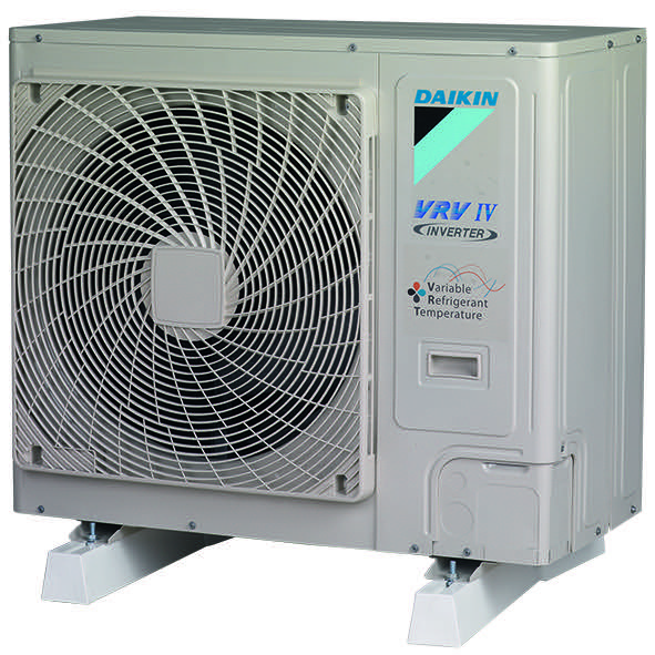
Figure 2: An 823mm-high external refrigerant R410a unit, capable of providing more than 12kW cooling/heating acting as a heat pump and supplying variable refrigerant temperature control (Source: Daikin)
Some of the key aspects of development and application of VRV/VRF systems have been discussed in previous CPD articles (including January 2015 and March 2014, available at www.cibsejournal.com/cpd/modules). The system is based around a heat-pump arrangement that allows heat to be directed to where it can be most effectively used. This will allow, for example, the shifting of heat from a room that requires cooling to one that demands heating or – when there is no need for any space heating – usefully to preheat the domestic hot water store. Through the effective redirection of heat, as well as making use of the heat pump to move heat to and from the external space, installed systems can operate with high values of seasonal energy efficiency ratio (Seer – for cooling) and seasonal coefficient of performance (Scop – for heating). This can make a positive contribution to the environmental ‘rating’ of the building, compared to systems that do not recover – and redirect – the thermal energy. Not only does this reduce operating costs but, by improving the building’s certificated environmental performance, it can also improve the opportunity to lease a building and increase its value in the sales and rental markets.10
Enhancing the component performance of VRV/VRF
The VRV/VRF system is driven by the compressor, which is typically housed – together with a heat exchange coil and controls – in what’s traditionally termed the ‘condensing unit’, although it may well provide an evaporating function when the overall system requires heating. This is normally sited adjacent to – and outside – a building. In existing (as well as some new) buildings, locating the condensing unit can be difficult practically, for either aesthetic or noise reasons, so it is beneficial to reduce the size and noise output of these units. A major VRV/VRF manufacturer11 reports that one of the most frequently requested developments is that the height of ‘condensing units’ be lowered so that they can be more easily obscured – while, of course, maintaining appropriate space around the unit to maintain effectiveness.
Manufacturers continuously develop their products to improve performance and give them a competitive edge. For example, changing the compressor from a simple rotary compressor to a more efficient swing rotary type, as shown in Figure 1, can improve efficiency with no exterior change to the unit – effectively providing increased capacity with no increase in size.
Going Dutch
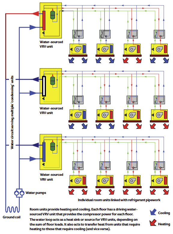
A ground-loop water-sourced VRV (Figure 3) was recently implemented in the new multi-storey Park Phi complex of buildings at Enschede in the Netherlands. The VRV has been applied in conjunction with other technologies – including ground thermal storage systems, solar panels and grey-water systems – to deliver a BREEAM Excellent-rated building. The integrated systems and integral heat pump in the water-sourced VRV systems (one per floor) allow the heat to be shifted around the building and into – and out of – the ground loop that is embedded in a massive thermal store of sand. The combination of systems is claimed to have provided an 80% reduction in energy use compared with a standard modern office complex of the same size.
The fabrication method of the compressor can also affect its size. For example, by using injection moulding with a semi-molten metal, which is then rapidly cooled, the compressor material can be made significantly stronger – and thinner – than a traditionally cast compressor casing. The resulting compressor will be smaller for a given load, and the external ‘condensing’ unit may be more compact, as shown in Figure 2.
As discussed in the January 2015 CPD, the control regime for such systems has been developed to allow for modulation of the evaporating and condensing pressures (and temperatures), to maintain design conditions while reducing input energy. This has evolved further to optimise refrigerant flow rates and pressure drops, so that the compressor work is reduced. These combine to allow systems to satisfy a greater diversity of load without increasing the size of the unit.
In some cases, it is more convenient, practically, to separate the traditional components of the external unit so that the compressor may be housed at a position where, for example, it can be acoustically shielded or positioned in a less sensitive plantroom. The external coils and fans can then be located remotely where they have proper access to the external air, either directly or via ductwork. Using this arrangement, a manufacturer has developed its system12 so that the compressor and ‘external’ heat exchanger modules can, typically, be up to 30m apart. The manufacturer’s choice of fan for moving the outdoor air through the heat exchanger will determine how far – and how efficiently – the air can be ducted, realistically. Traditionally, a forward curve fan has been used in such systems. The forward-curve fan is generally less efficient (typically around 70%) than its backward-curved equivalent (typically 80+% efficient), and it is less well suited to the higher pressure drops of ducted air systems, so is unlikely to be appropriate when the ‘outdoor’ coils have a ducted air supply.

Figure 3: A representation of the type of system applied in the Dutch multi-storey Park Phi complex
In conjunction with the flexibility offered at the outdoor unit, a combination of control boxes and manifolds can direct the flow through the pipe networks so that a single external unit can provide concurrent heating and cooling across multiple zones in a building. The energy is transferred around the building in small-bore (insulated) refrigerant pipework. The indoor units are the only parts that the occupants of the building can normally see – although, by using refrigerant-fed internal units rather than chilled water-based fan coils, they can be smaller and less intrusive. Indoor units can be more than 60m – and several floors – from the external unit. Any designs carrying refrigerant through occupied spaces must be mindful of the requirements of BS EN 37813, which sets standards to limit harmful levels of refrigerants. Properly designed, installed and operated VRV/VRF systems readily meet these requirements.
The indoor and outdoor units of a VRV/VRF system contain motors and fans and/or compressors, which will all generate noise and vibration. However, the transmission of this can be significantly reduced through the careful design and installation of the units. This includes resilient mountings for the motors and sound-insulating enclosures – and, potentially, sound-absorbing materials on the ducted air paths.
Through acoustic analysis and design, a manufacturer11 has developed refrigerant distribution boxes (used in the occupied space) that have a reduced overall noise level – by 10 dBA at 1.5m – compared with similar products.
Water-sourced heating and cooling for VRV/VRF
VRV/VRF is traditionally associated with outdoor air heat exchangers, providing a source of heat when the outdoor coil is acting as an evaporator, or a heat sink when the outdoor unit is truly acting as a condensing unit. This unit can be replaced with, or augmented by, one that is designed to exchange heat with water rather than air. Water can offer significant advantages, by supplying increased availability of heat, both as a source and sink. This can lead to smaller, quieter, single or multiple VRV/VRF ‘condensing’ units, with smaller refrigerant charges that can be readily installed in plantrooms at practically any level of the building (or externally), connected to the water source by pipework. The system that excited interest at the recent COP21 Paris conference was the provision of city-wide water mains delivering a thermal resource that could, for example, supply water-sourced VRV/VRF systems. Alternatively, water could be drawn from sources such as wells, ground loops and boreholes.
© Tim Dwyer, 2016
References:
1 Interview with David Garwood of BSRIA, accessed 3 December 2015.
2 Niemeläa, R, et al, ‘The effect of air temperature on labour productivity in call centres – a case study’, Energy and Buildings, Volume 34, Issue 8, September 2002.
3 Lan, L, et al, ‘The effects of air temperature on office workers’ well-being, workload and productivity-evaluated with subjective ratings’, Applied Ergonomics, Volume 42, Issue 1, December 2010.
4 Seppänen, O, et al, Effect of Temperature on Task Performance in Office Environment, Helsinki University of Technology, 2006.
5 Lakeridou, M, et al, ‘The potential of increasing cooling set-points in air-conditioned offices in the UK’, Applied Energy, Volume 94, June 2012, pp 338–348.
6 Cold economy, The Guardian, accessed 3 December 2015.
7 CIBSE TM55 Design for Future Climate: Case Studies, CIBSE, 2014.
8 Yamamoto, Y, Development of High Efficiency Swing Compressor for R32 Refrigerant, Purdue University, 2014.
9 The Little Black Book, Property Construction Benchmarks, 2011-2, Franklin and Andrews, 2011.
10 Is BREEAM Outstanding worth it?, accessed 3 December 2015.
11 Private communication with Martin Passingham, Daikin UK.
12 Daikin VRV-i product information, accessed 3 December 2015.
13 BS EN 378-4:2008+A1:2012 Refrigerating systems and heat pumps. Safety and environmental requirements. Operation, maintenance, repair and recovery.
