The supply of appropriate, known air flowrates through mechanical ventilation and air conditioning systems in commercial and industrial applications is fundamental to effective system operation. This CPD module considers the characteristics of moving air and explores the application of pressure-based airflow measurement as a means of assuring air flowrates.
A typical assumption at the design stage is that air flowrates in the installed systems will match the design intent; however, unless the systems are suitably controlled, this is unlikely to be the case. Poor control will, at best, lead to less-effective operation, poorer indoor air quality (IAQ), increased energy use and – for more critical applications, such as fume and smoke extraction – a potential health and safety risk to building occupants.
Whether a system is operating at full or reduced air flowrate, it is important to ensure there is an appropriate supply of outdoor ventilation air to maintain IAQ by diluting indoor pollutants, such as carbon dioxide (CO2), dust, allergens, microbes, and volatile organic compounds (VOCs). In most ventilation systems, there are minimum flowrates that are required to ensure adequate air distribution that not only maintain IAQ parameters, but – as discussed in the September 2022 CIBSE Journal article1 exploring Khankari’s work – also may limit the spread of contaminants from a source.
Additionally, properly controlled airflow can be critical in smoke management during a fire, aiding safe evacuation and minimising smoke-inhalation risks. A well-controlled system can readily adapt to changes in building usage or occupancy, ensuring long-term flexibility in working practices while continuing to meet ventilation standards and comply with health and safety standards.
Precise control of airflow ensures that only the necessary amount of air is moved, reducing the energy required for fans and other components. For example, the key benefit provided by variable air volume (VAV) systems is that, by adjusting airflow based on demand, VAV can provide significant fan energy savings compared with constant air volume (CAV) systems.
When using a CAV system, zoning may be used to close off, or reduce, the supply of ventilation air to cater for the specific needs and preferences of different occupants or activities. Zoning allows different areas of the building to be controlled independently and, potentially, provides the opportunity to fully isolate areas of the building that are not in use. This would enable the supply and extract fans to operate at a slower speed. As well as reducing the volume flowrate of the air that needs to be moved by the fan, this also reduces the load on heating and cooling equipment.
System and sub-system pressure drops will be dependent on the characteristics of the ducted system, including roughness and geometry of the ducting materials, the number and type of fittings, such as constrictions or bends that disrupt the air path, as well as the properties of the air itself.
The relationship between air pressure drop, Δp (Pa), and volume flowrate, Q (m3.s-1), of air flowing through a typical commercial heating ventilation and air conditioning (HVAC) ducted system can be normally characterised as proportional, so Δp∝Q2. So, for air flowing through a specific resistance, R, such as a filter or a purpose-made measuring station, Δp = RQ2, where R is a constant of resistance that is related to the particular item (for example, the filter, or the measuring station). If the measuring system is calibrated with respect to the specific resistance, R, then the flowrate may be obtained from Q= (Δp/R)0.5.
Pressure differential sensing (measuring the Δp) is widely applied in HVAC systems as the means of referencing air flowrates. This may be to directly measure pressure differences across components such as air inlet louvres, filters, ducts, or heat exchangers, or be used in association with fully calibrated devices such as venturi measuring stations to provide measurements of air flowrates.
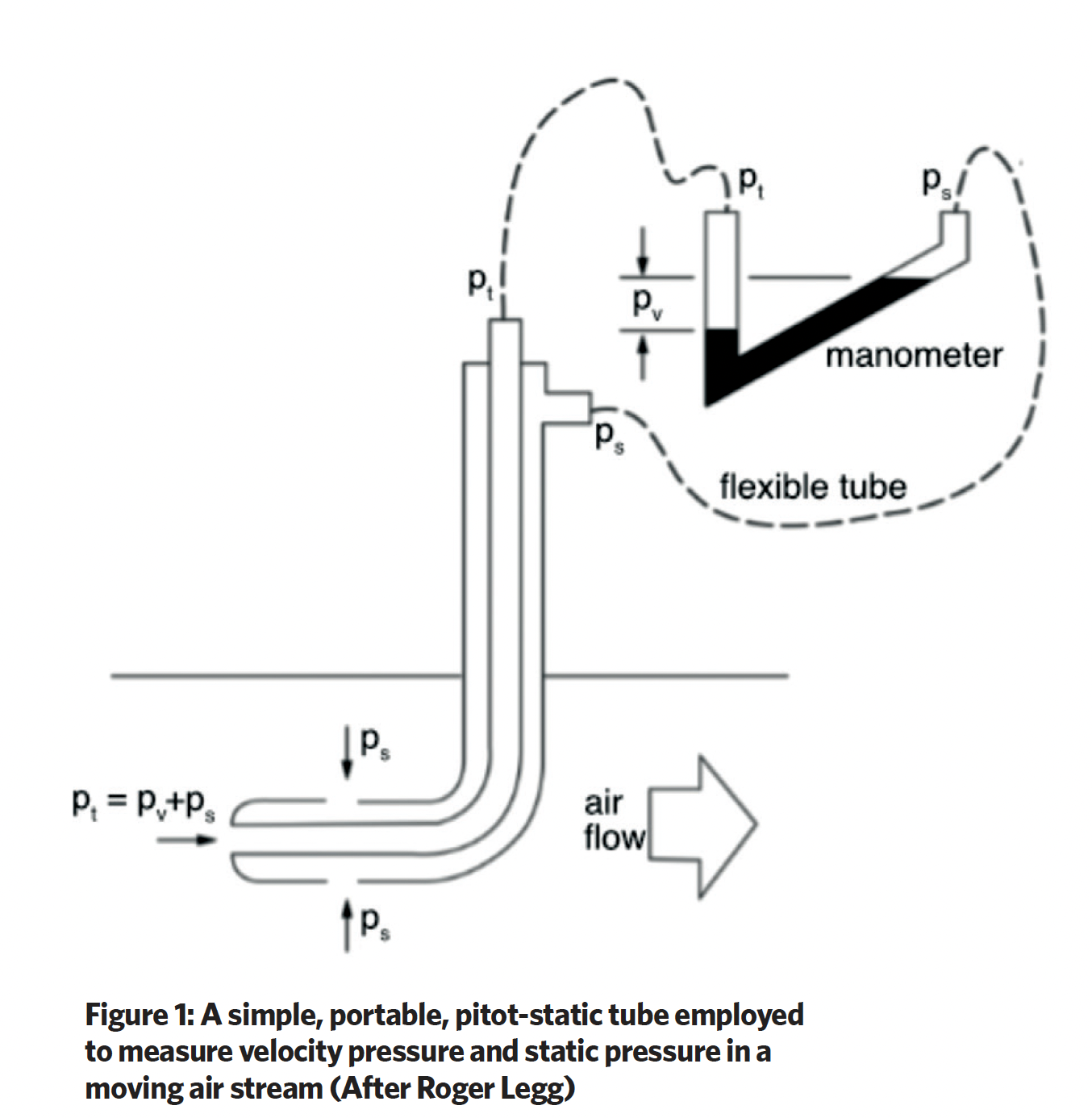
The total pressure, pt, (Pa) in a moving airstream is the sum of the velocity pressure, pv, and static pressure, ps, so pt = pv + ps. The velocity pressure may be readily established as pv = pt – ps. This can be obtained using a liquid manometer, as illustrated in Figure 1, which is connected to a pitot-static tube that is held in the duct. Since velocity pressure may be calculated from pv = 0.5ρ c2, where ρ (kg.m-3) is the air density (typically assumed as 1.2kg.m-3), the velocity, c (m.s-1), of the air can be obtained from (2pv/ρ)0.5. And from this, the volume flowrate, Q, may be obtained by multiplying the duct area (m2) by the average air velocity across the duct.
In most HVAC applications – other than when the air passes through a heating or cooling process – the temperature of the air in a particular duct run, along with its density and viscosity, are assumed as nominally constant, so the volume flowrate (and, of course, the associated mass flowrate) remain constant.
Devices such as the pitot-static tube only provide a point measurement. To gather more representative pressure data on a continuous basis, purpose-manufactured measuring devices may be employed. Historically, these have been applied in specialist systems when specific needs demand continuous airflow measurement, such as maintaining required air volume or room air pressure in laboratory or process environments to ensure positive movement of air and contaminants.
However, ensuring adequate outdoor air supply is not limited to specialised applications. For example, any systems that vary the air flowrate require careful design and operation to maintain optimal outdoor air fractions as the total flow modulates. By actively and accurately monitoring volume flowrates of outdoor air, and total and individual zone flows, the control system is able to modulate outdoor and recirculated air proportions effectively.
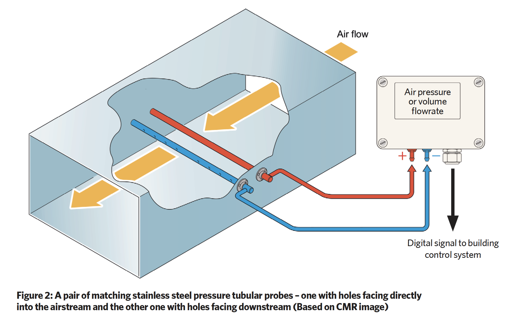
An example of a commercially available flow pressure sensor, illustrated in Figure 2, is a pair of identical stainless steel pressure probes that may be mounted in a duct. One probe measures the total pressure, while the other measures the static pressure. Unlike the simple pitot-static tube, the probes continuously collect pressure signals across the whole width of the duct and, through an associated electronic pressure transducer, may be precisely calibrated for a particular application.
It is important that the sensor remains stable across the operating range, since a drift of just 1Pa or 2Pa – particularly at the lower end of the range – can cause a significant error in the measurement of the air volume. For example, if designing a system with an air velocity of 4 to 5m.s-1, with a resulting velocity pressure of under 15Pa, the error in pressure measurement could exceed 10%. This error may be magnified in systems that employ two separate sensing devices to maintain small positive or negative pressures compared with an adjacent, sometimes outdoor, space.
Applications that rely on a small pressure difference to operate effectively include those positively pressurised to prevent ingress of contaminants, such as an airport terminal building designed to prevent the ingress of fumes from aircraft engines, or an office building in a polluted city centre that might otherwise be subject to vehicle pollution. Commonly encountered minimally negatively pressurised zones include hospital critical care spaces, clean rooms and laboratories that all rely on a robust pressure control to prevent cross-contamination. If the pressure sensors drift by just a few per cent in either the supply and extract systems, there is opportunity for significant pressure deviations leading to potential contamination.
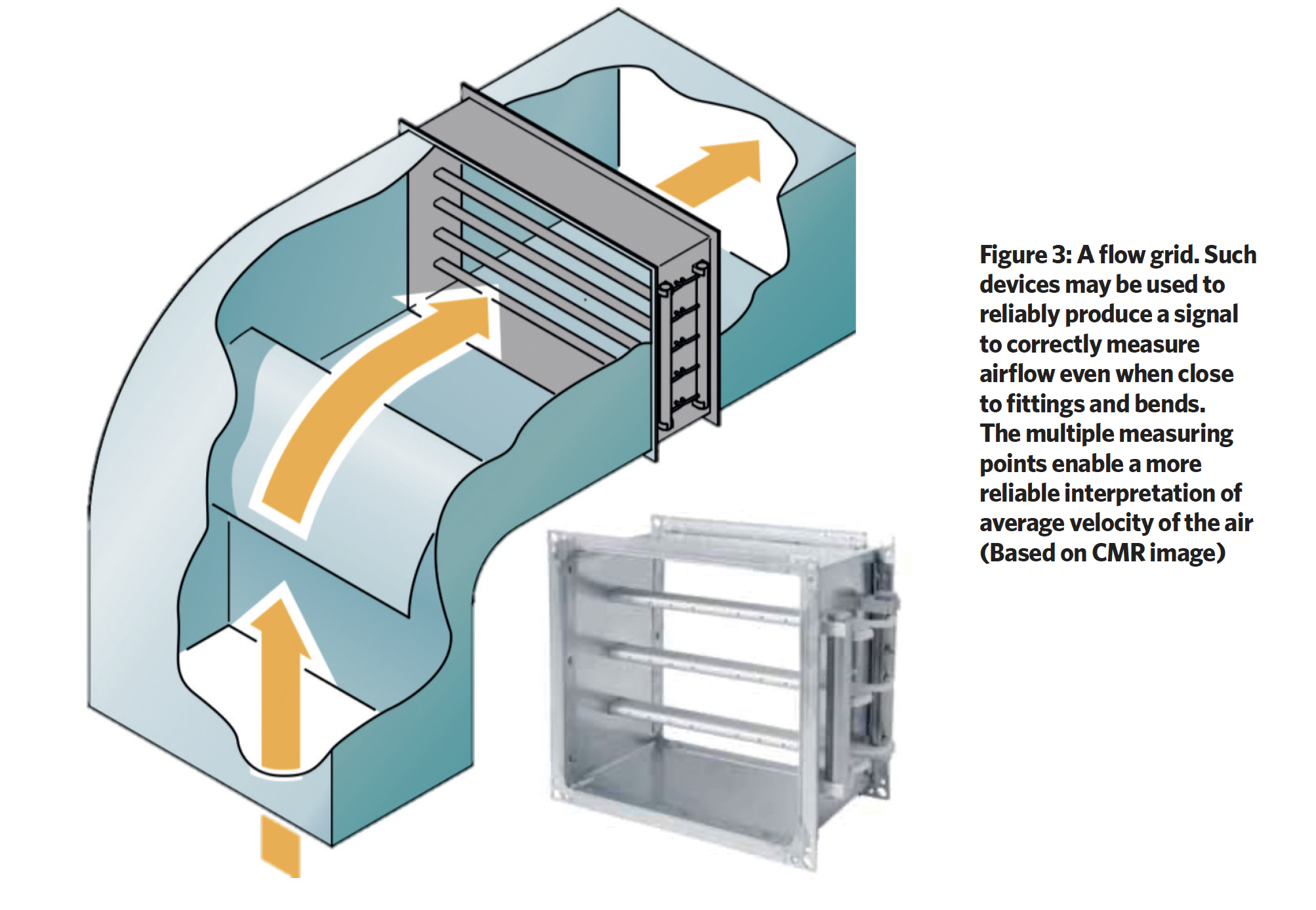
Permanent installations, which require more exacting measurements, can incorporate frameworks known as velocity or flow grids, which are designed to capture measurements across a representative section of the flow area, as shown in Figure 3. These tubular grids are strategically populated with holes to obtain a representative average pressure. Total and static pressure are measured independently through holes drilled into sampling tubes at specific orientations.
Such grids come with calibration factors that translate measured pressures into velocities or volumetric flowrates, or are supplied as part of a package with a matched microelectronic transducer and signal conditioner. Their design allows for a stronger pressure signal compared with single-probe measurements, enhancing resolution and reducing potential errors, achieving measurement accuracies within ±0.2% of the full scale. They also offer a significant benefit, as with appropriately matched transducer and signal conditioning they maintain responsiveness at very low pressures, allowing very low air velocities, approaching 0m.s-1.
The pressure signals from the measuring points then need conversion into a form that can be used by the control systems. This requires a transducer that, in commercial HVAC, commonly employs sensors based on piezoresistive or capacitive principles. However, the reliable, but less well-known, variable reluctance (VR) sensor, has a well-established pedigree in close-control ventilation systems such as those used in laboratories and microchip fabrication plants. Such sensors have proved robust – a manufacturer2 reports such sensors with a copper beryllium diaphragm are still providing reliable output after more than 30 years’ continuous use.
Variable reluctance sensor
Typically known as a VR sensor or magnetic pickup, these sensors detect the position of moving metal objects. They operate on the principle of variable reluctance, which is the change in magnetic resistance caused by the movement of a ferromagnetic material in proximity to the sensor. The key components of a basic VR sensor are a permanent or electromagnet to provide a magnetic field; a moving metal object (known as a ferromagnetic ‘target’) that, when it moves, induces a voltage, and potentially a current, in an adjacent coil because of the changing magnetic flux.
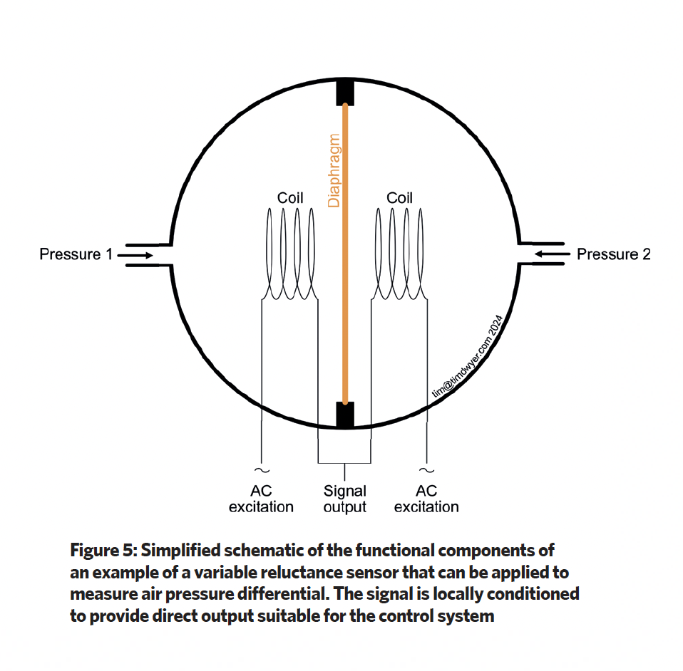
Figure 5 shows the basic components for a VR pressure differential sensor, as used in HVAC applications. It consists of a ductile ferromagnetic diaphragm that provides a thin, movable membrane separating two air chambers. The coils are positioned on either side of the diaphragm.
When a pressure difference exists across the diaphragm, it deflects. This movement alters the magnetic flux path between the core and the coils. The reluctance, which is the resistance to magnetic flux, changes based on the diaphragm’s position. The VR sensor coils are typically driven by an alternating current (AC) signal. The varying reluctance caused by diaphragm deflection affects the induced current in the coils. This change in current can be processed by local microelectronic circuitry to provide a calibrated digital or analogue output that corresponds to the pressure difference.
VR sensors can handle the wide range of pressure differential commonly encountered in HVAC systems and are able to detect small changes in pressure. The simple design, with minimal moving parts, adds to their reliability and long lifespan, while their small size allows for easy integration into various HVAC components. The key component is the diaphragm – the material for this must maintain ductility and integrity over extended periods of use.
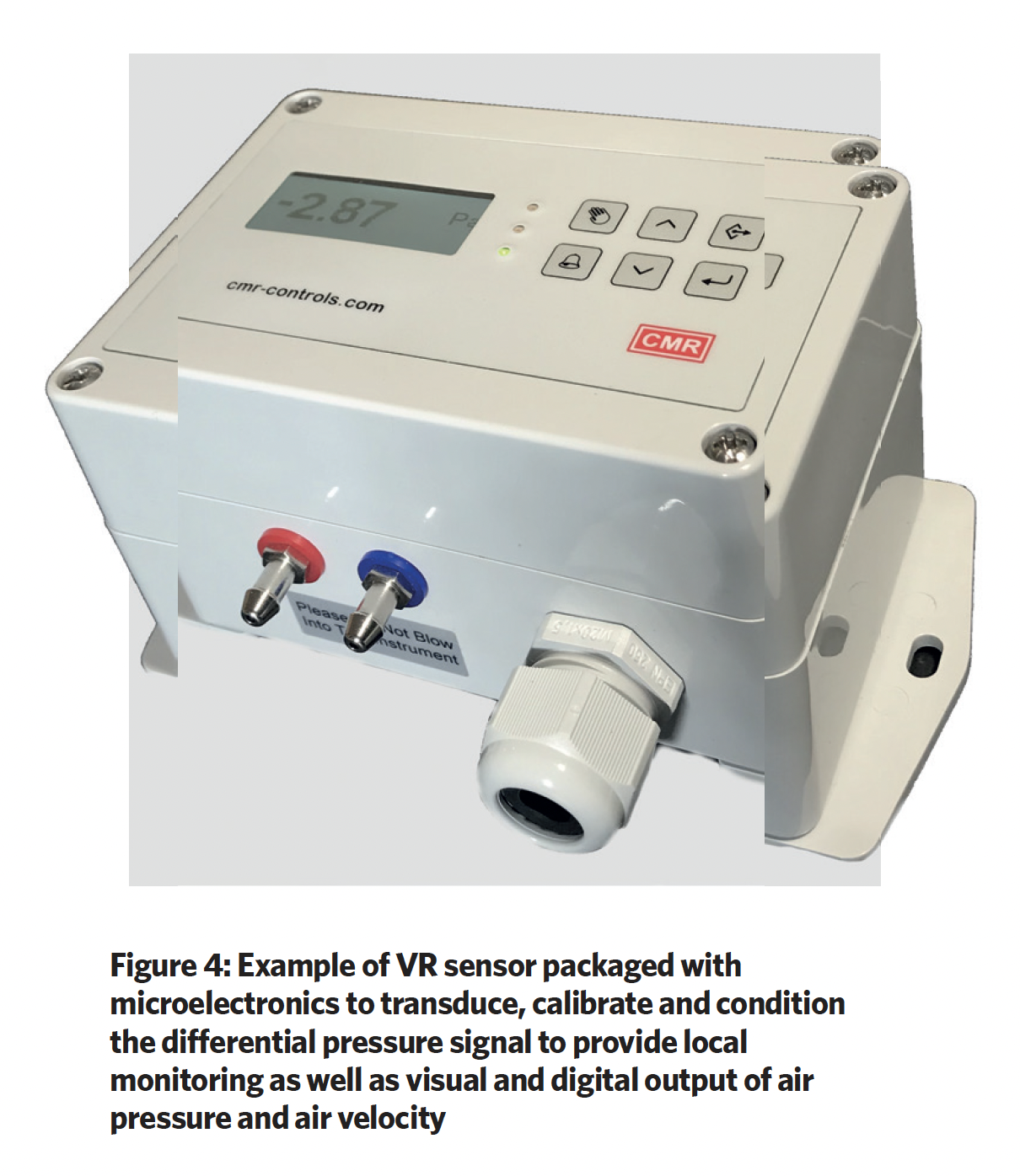
The two pressure connections shown in Figure 5 are connected by tubes to the pressure outlets of the measuring device, and the diaphragm deflects in response to any pressure difference across it. When close-coupled with packaged local microelectronic conditioning, as in the example unit shown in Figure 4, the digital output may be transmitted to the local building management system (BMS) – using a protocol such as RS485 for Modbus connectivity – to ensure that the BMS receives the measurement that is representative of the sensor output (rather than employing uncertain BMS-based analogue-to-digital conversions). VR sensors can provide a cost-effective option for pressure differential sensing in HVAC compared with some alternative technologies, particularly when total life-cycle energy use, operating costs and environmental impact are considered.
Closely controlling the airflow in a building ventilation system offers significant benefits, from energy efficiency and cost savings to enhanced indoor air quality, thermal comfort and safety. These advantages make it a crucial aspect of modern building design and operation – and worthy of careful consideration when developing ducted air-distribution systems for HVAC applications.
About the author
Tim Dwyer