Today, where energy efficiency of all systems and plant is vital in reducing carbon emissions, it can be a useful tool to understand how equipment functions. Refrigeration has often been regarded as a necessary evil and many of its system characteristics a mystery. CIBSE has produced the Knowledge series of publications, which provides overviews and applications of many topics including refrigeration. The publications concentrate on application rather than theory.
In this article a brief section shows the basis of the refrigeration cycle, with references to further reading for additional study.
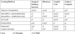
The vapour compression, or mechanical refrigeration system is the most common method of cooling in air conditioning, but it is worth realising that there is a number of different cycles or systems that produce cooling. Table 1 is a subjective comparison – for further reading go to the CIBSE Guides B2 and B4.
Vapour Compression Theory
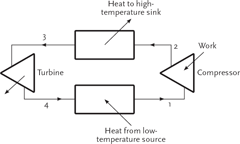
The vapour compression refrigeration cycle is based on the reverse Carnot cycle. The cycle transfers heat energy from a low to a high temperature level and earns the name ‘Thermal Pump’. Figure 1 illustrates the cycle components involved. The cycle requires four basic components: low temperature heat exchanger (evaporator); compressor; high temperature heat exchanger (condenser); and a turbine (replaced by a pressure reducing device in practice).
Table 1: Cooling Methods
Figure 1 Components of Carnot cycle
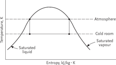
Figure 2 shows the processes on a temperature/entropy diagram where the cycle is placed within the liquid/vapour region of the working fluid (refrigerant).
Figure 1:
- 4 – 1 Isothermal heat addition to the cycle, where the working fluid is heated and vapourises from a liquid to a vapour at constant temperature T1. This is the process that cools air or water in a air conditioning system.
- 1 – 2 Isentropic compression, where the working fluid is raised in temperature from T1 to T2.
- 2 – 3 Isothermal heat rejection from the cycle, where the working fluid is cooled and condenses from a vapour to a liquid, at constant temperature T2.
- 3 – 4 Isentropic Expansion, which requires the use of a turbine.
This cycle is theoretical and provides the maximum possible efficiency, which is useful to compare with an actual cycle. In practice, in Figure 2, it is necessary to move point 1 to the right until it reaches the saturated vapour line or further to become slightly superheated, in order to prevent liquid refrigerant entering the compressor. This means that the initial part of the condensation process 2 – 3 will be taken up with desuperheating, before condensation occurs at the condensing temperature T2.
Figure 2 Thermodynamic processes
The expansion process 3 – 4 requires a turbine and for the resulting work to be used for the compression process. This is not cost effective at present, so the process is substituted by a simple throttling or pressurereducing device such as an expansion valve (this process is described as constant enthalpy). However, this results in point 4 moving to the right, effectively reducing the cooling effect of the refrigerant.
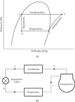
For practical use, the vapour compression cycle is best represented on a Pressure/Enthalpy diagram, illustrated in Figure 3. The diagram makes it convenient to obtain properties such as enthalpies, pressures, temperatures, specific volumes and entropies, all necessary when making cycle calculations.
Taking an air conditioning example where air is cooled to 15°C and the ambient air available for heat rejection is at 30°C, the evaporator is an extended surface or finned configuration heat exchanger. Refrigerant liquid circulates through the evaporator tubing and must be at a lower temperature than the air, say 8°C. The heat exchanged from the air as it is cooled vaporises the liquid refrigerant. This takes place at constant temperature with most refrigerants, so the refrigerant temperature stays at the temperature we have specified, 8°C, until all the liquid has evaporated. This evaporating temperature can be changed by raising or lowering the pressure of the refrigerant. Outside of refrigeration we would identify this property as the saturation temperature and relate it to pressure. The relationship is different for every fluidused as a refrigerant, and if we use R134a – a common refrigerant today – the pressure in the evaporator will be 3.87 bar absolute.The compressor has two functions: to pump the refrigerant around the system; and to raise its pressure. The compressor capacity determines the flow rate of refrigerant, and should be the same as the evaporation rate in the evaporator, which is a function of the cooling load on the evaporator. The compressor discharges high-temperature, high-pressure refrigerant at point 2 in Figure 3. The temperature reached will depend on the pressure ratio of the compressor and the refrigerant being used. In our example the discharge temperature will be about 80°C, but in some applications this could rise to 130°C.
The aim of the cycle is to restore the refrigerant to low-temperature liquid that can be fed back to the evaporator. This is done in two stages – condensing and pressure reducing. The highly superheated vapour enters the condenser at point 2. In our example this is a finned tube heat exchanger which uses ambient air at 30°C to cool the refrigerant in the tubing of the condenser.
Heat is rejected from the refrigerant into the ambient air. The majority of the heat rejection is latent condensation from the refrigerant at a temperature above that of the ambient air. This is called the condensing temperature and, as a rule of thumb in this example, the condensing temperature will be 15K above the ambient air temperature, or 45°C. For this to take place, the compressor needs to raise the pressure of the R134a to 11.5 bar absolute. The refrigerant leaving the condenser at point 3 will be liquid that has been subcooled by about 5K, that is, at a temperature of 40°C and still at 11.5 bar absolute. Note that about 10% of the heat rejection is desuperheating of the refrigerant entering the condenser and has the possibility of being used for heating.
The refrigerant is then reduced in pressure through an expansion device from points 3 to 4 in Figure 3, entering the evaporator as a mixture of liquid and vapour at 8°C and a pressure of 3.87 bar absolute. Note that the expansion process results in the formation of ‘flash gas’ and in most air conditioning applications will amount to about 20% of the mixture by weight. For the majority of applications the expansion device is normally a valve, thermostatically or electronically operated, which controls the refrigerant flow rate to the evaporator, sensing evaporator outlet superheat. This is an important function that ensures the evaporator tubing receives the optimum amount of refrigerant and also protects the compressor from liquid refrigerant entering its suction port. Centrifugal compressor water chillers use a ‘flooded’ type evaporator where the refrigerant level is controlled, as opposed to suction superheat.
Figure 3 Practical components and Pressure/Enthalpy cycle
Efficiency of the Cycle
The efficiency of the vapour compression cycle is called the Coefficient of Performance (COP) and strictly speaking should include the subscript ‘c’ to denote the cooling mode – COPc. The maximum efficiency that this cycle can attain is the Carnot Cycle COPc
where Tc is the Condensing temperature and Te is the Evaporating temperature, both in absolute temperature or Kelvin.
For example, a system has an evaporating temperature of 5°C and a condensing temperature of 45°C. Using the above equation, the COPc is 6.95. In practice, the actual system COPc will be about 50% of that, or 3.5, due to inefficiencies within the practical cycle.
In the UK and Europe we express COPc as an Energy Ratio, equal to:
If the COPc is 4.0, the Refrigeration Unit will produce 4.0kW of cooling per kW of electrical consumption by the motor. To be more realistic, the power consumption should include other electrical items such as condenser/AHU fans and circulating pumps associated with producing the cooling capacity. A seasonal COPc may also be useful, as annual energy consumption can be compared with an annual cooling capacity and incorporated into annual energy costs for the building or application. In fact, this is a requirement for the input data of the EPBD iSBEM assessment calculation. It is defined as the Seasonal Energy Efficiency Ratio (SEER) in the Part L non domestic heating, cooling and ventilation compliance guide, May 2006 section 9.
The major factors that affect the efficiency of a refrigeration system are:
- The evaporating temperature
- The condensing temperature
- The type of refrigerant used
- The type of equipment used, such as compressor, evaporator, etc
- The system controls
- Correct maintenance of the system
The choice of evaporating and condensing temperatures has the greatest effect on COP and therefore running costs. A 1K rise in evaporating temperature or drop incondensing temperature results in a 2 to 4% increase in COP.
The evaporating and condensing temperatures are determined by the cooling temperature requirement and the heat rejection cooling temperature available. For example, a water chilling application where the chilled water temperature needed is 6°C, and air cooled condensers with maximum design air dry bulb temperature of 30°C.
We would expect an evaporating temperature of 1°C and condensing temperature of 45°C, resulting in an operating COPc. If the evaporating temperature could be raised by 1K and the condensing temperature reduced by 1K, performance of the system will increase by between 4 and 8 per cent – a considerable amount.
The design and selection of the evaporator and condenser can play a significant part. These heat exchangers are capacity rated by the equation
where
- Q is the heat transfer rate in kW
- U is the overall heat transfer rate in W/m²K
- A is the heat transfer surface area in m²
- LMTD is the log mean temperature difference in K
For the evaporator in the above example, U and A remain constant and Q becomes directly proportional to LMTD, which can be taken as (water out – evaporation temperature) for comparative purposes. If we try to operate at a lower evaporation temperature, say -1oC, there is a danger that the water freezes, but we will increase the Δt across the evaporator. This means we could reduce surface area/size/cost, but the penalty is 4 to 8% lower efficiency. If we want to increase efficiency, we need to raise the evaporating temperature, reducing Δt, but this will require more surface area at the cost of space and expense. You may want to follow up this reading with the references indicated below.
© Terry Welch


