The U Value Calculation
As any student of building services or architectural engineering will know, to determine the U value the individual thermal resistances, R (m2K/W) of the layers that make up the structure must first be determined from R = d/λ, where d = thickness or depth of the material (m) and λ = thermal conductivity of the material (W/mK). Example values of thermal conductivities (at standard moisture content and temperature) are given in Figure 1 and extensive tables of these are to be found in CIBSE Guide A 2006 – Section 3.

Figure 1: Example of standard thermal conductivities
The ‘n’ individual resistances that make up a structure are combined with the inside and outside surface resistances, Rsi and Rse, (m2K/W) to give a total resistance, ΣR, for the element ΣR = Rsi + R1 + R2 + ….. + Rn + Rse m2K/W
The U value is simply the reciprocal of the total resistance, ie 1/ΣR, and then the basic building fabric heat transfer coefficient is Σ(A U) where the area, A (m2) is the area of each individual element that has a respective thermal transmittance of U (W/m2K).

Figure 2: Simple wall structure
And so it looks quite straightforward. However when considering the individual layers that make up the structure, very few of them are actually consistent across the whole area of the structure. Take, for example, the simplified four layer wall in Figure 2. The outer brickwork is made up both of bricks and mortar and the blockwork is also a mix – this time of lightweight concrete blocks and mortar. Of course the bricks and blocks themselves are not totally homogenous as they will contain small air spaces and materials that differ across each piece of masonry. However, in terms of thermal calculations, such ‘minor’ internal irregularities are normally ignored, and only considered for air pockets in insulating materials that may be large enough to allow air convection currents within the material, reducing the thermal resistance. (BS 10456[1] explains the method to undertake this analysis).
So considering the brickwork layer, and referring to the data in Figure 1, the exposed bricks have an R of 0.105/0.77 = 0.136 m2K/W and the exposed mortar 0.105/0.94 = 0.112 m2K/W. CIBSE Guide A recommends that if the R values differ by no more than 0.1 m2K/W then the R value for the major element may be used (and in this case the difference is 0.136 – 0.112 = 0.024 m2K/W), so the R for this layer is taken as 0.136 m2K/W.
If the difference exceeded 0.1 m2K/W, then the layer is said to be thermally ‘bridged’ and a more complex procedure must be used (that will be described later). A general rule is that mortar joints can be treated as having insignificant influence[2] when the thermal conductivity of the masonry units is greater than 0.5 W/mK.
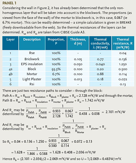
If the concrete blockwork layer is examined the light concrete block R = 0.100/0.20 = 0.500 m2K/W and the protected mortar R = 0.100/0.88 = 0.114 m2K/W. Clearly the difference between the R values exceeds 0.1 m2K/W and so the blocks are said to being thermally bridged by the mortar.
The effect of a thermally bridged structure is that the flow of heat may not be assumed as going directly from one side to the other (unidirectional) but will also pass sideways between the different materials. Since the simple U value calculation is based on unidirectional flow, this more complex heat flow pattern needs to be solved by computer methods (numerical analysis) or by applying the ‘Combined Method’[3]. This method uses the mean of two extreme values of thermal resistance (known as the upper, RU, and the lower, RL) of the heat flow paths through the structure to provide the bridged thermal resistance, Rb. The upper limit, RU, is the resistance that allows for simple unidirectional heat flow and is determined by proportioning the resistances of the different heat flow paths with respect to their area. (And this calculation alone was the method used historically when calculating non-homogenous U values). The lower limit of thermal resistance, RL, is a value that allows for sideways flow of heat through the structure. The actual resistance will fall somewhere between the two extremes and a mean of the two values is taken as a reasonable estimate of the overall bridged resistance, Rb.
The actual calculations appear complicated (especially where there are multiple bridged layers) but are actually quite straightforward (if sometimes lengthy). An example calculation for the wall in Figure 2 is given in panel 1. Elements in real constructions can be rather more complicated, having several nonhomogenous layers. CIBSE Guide A3 2006 Section 3.11.2 has more extensive examples and several are available in “Examples of U-value calculations using BS EN ISO 6946:1997”[4] freely available from the UK government DCLG website.
However it is not always easy to judge how to approach the calculation and to know where simplifying assumptions can be applied. The excellent document ‘Conventions for U-value calculations’ BRE Report BR 443:2006 can be freely downloaded from the web and has clear and extensive guidance on the practical approach required when examining U value calculations for a whole range of real building elements. This information is particularly useful at the early stages of design when generic materials and construction techniques are envisaged. This not only includes guidance as to the elemental considerations (eg how to determine appropriate resistances for foam faced blocks, or plasterboard on dabs) but also how to establish the U value for constructions complicated by such things as recessed light fittings and loft hatches. BR 443 includes extremely helpful advice on factors to be considered when determining U values for walls, roofs, floors, glazing and doors.
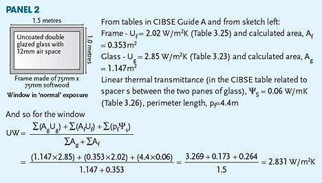
One of the concepts applied in BR 443 that was introduced to CIBSE Guide A in the 2006 revision (and still unfamiliar to many) is that of the ‘linear thermal transmittance’, Ψ-value, or the psi-value (W/mK). This is used to establish the variation in heat flow that occurs at the junctions between the various building elements, for example where a wall joins a roof, or a piece of glass connects to a frame. Because of more complicated geometries and materials used at the junctions, the overall U value of the construction will be affected, and the Ψ-value represents the difference in heat flow through the junction compared to that through the separate connecting elements. This is illustrated by the unevenness of the temperatures across the lower section of an example window (Figure 3 and Figure 4) caused by the increase in U value at the junctions. The ‘cooler’ green area can be seen extending into the area where the inside pane of glass meets the frame. (Apart from the additional heat loss, this may cause problems with condensation and subsequent mould growth.) The practical impact may be investigated through thermal modelling or by applying tabulated values from the CIBSE Guide. A useful tool, ‘Therm’, may be freely downloaded from http://windows.lbl.gov/ software/therm, and will allow 2-dimensional analysis of building structures and windows, so that potential high U values may be avoided.

Figure 3: Lower section of example double glazed window with a frame manufactured from two principal materials

Figure 4: Simulated temperature profile through lower section of double glazed window
Psi-values are available for specific construction types, eg roof joints, floor to wall sections and glass to frame connections. Accounting for thermal bridging at edges has become increasingly important as the requirements for building thermal performance have become more stringent, and consequently the main elements have higher thermal resistances increasing the relative impact of losses at edges and junctions. The supporting documents to the various UK Building Regulations recommend using accredited construction details[5] [6] (ACDs) to ensure that the edge losses are minimised.
The term ‘y-value’ is used to describe the sum of (length × Ψ) for all junctions in a building envelope divided by the total area of external elements, and provides a performance metric for thermal bridging, (not to be confused with the ‘Y value’ that is the abbreviation for thermal admittance and completely different!)
As an example, the application of linear thermal transmittance as part of the U value calculation of a simple window is given in panel 2.
Each of the heat flow paths in a building requires appropriate analysis to ensure that the integrity of the predicted heat flows, and hence forecast building energy use, is maintained. Aside from the important issues identified in this article, others include the anomalies when considering heat flow through ground floors, air spaces and basements that will need careful consideration. CIBSE Guide A3 and ASHRAE Fundamentals Handbook chapters 17 & 18 are great places to find out more about this essential area of knowledge and application.
© Tim Dwyer
References
- BS ISO 10456:2007 Building materials and products – Hygrothermal properties – Tabulated design values and procedures for determining declared and design thermal values
- Conventions for U-value calculations BRE Report BR 443: BRE 2006, www.bre.co.uk/filelibrary/pdf/rpts/BR_443_(2006_Edition).pdf
- CIBSE Guide A 2006, Section 3.3.11
- Doran SM, and Kosmina L, ‘Examples of U-value calculations using BS EN ISO 6946:1997’ December 1999 www.communities.gov.uk/documents/planningandbuilding/pdf/133394.pdf
- Accredited Construction Details, DCLG, June 2007 www.planningportal.gov.uk/uploads/br/accredconbk.pdf
- Accredited Construction Details (Scotland) www.scotland.gov.uk/Topics/Built-Environment/Building/Building-standards/profinfo/techguide/acdscot


