
It has been almost 10 years since a CIBSE Journal CPD last discussed variants and applications of the ‘chilled beam’. In the meantime, the installation of beams has gathered pace, and they are now commonly seen in commercial applications. This CPD will revisit the basic functions of chilled beams, and explore the opportunities offered by the new generation of variable air volume (VAV) beams.
A prerequisite of maintaining safe and comfortable internal environments is good air quality, and this is typically achieved through ventilation. In commercial applications, mechanical ventilation will often also provide comfort cooling by supplying air at a lower temperature than room air.
When the outside, ambient air dry-bulb temperature is lower than the conditioned space dry-bulb temperature, this method is energy-efficient, as the outside air provides free cooling. Beyond the ventilative free cooling, moving cooling (and heating) energy around a building can be undertaken far more efficiently by pumping water (or other liquid) in pipes than by moving the same amount of heat in ducted air.
So, to increase cooling capacity and decouple air quality control from thermal comfort, ventilation systems are often combined with hydronic or variable refrigerant flow (VRF) systems, such as fan coil units (FCUs), radiant ceilings and chilled beams.
Chilled beams have coils that carry cool – or chilled – water and are mounted at high level in the conditioned space (principally in commercial buildings), and can be fully encased and suspended from the soffit or integrated into a false ceiling. The beams are typically referred to being either ‘passive’ or ‘active’ – as illustrated in Figure 1 and Figure 2.
Figure 1: Simplified passive chilled beam mounted above a perforated ceiling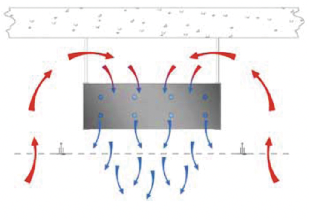
The cool coil exchanges sensible heat with warm room air as the air passes across and between the cooler coils (and their extended surfaces). The temperature of the surfaces of the beam must not fall below the dew-point temperature of the surrounding air, otherwise condensation is likely. Any dehumidification (latent cooling) required in the space must be undertaken by an associated central air supply system.
Passive chilled beams rely on natural convection currents in the room, driven by denser cool air being drawn downwards by gravity and so displacing the less dense warmer air to a higher level where it meets the cool coils of the chilled beam.
Active chilled beams are supplied with ducted ‘primary’ air from a centralised system that will generally be used to meet the ventilation air requirement for the space. The primary air is supplied from the beam’s primary air plenum through small outlets (traditionally ‘nozzles’) directed towards the air diffuser outlet of the chilled beam casing. These fast-moving primary air jets create a high-velocity pressure.
Figure 2: Simplified active chilled beam suspended from soffit, integrated into false ceiling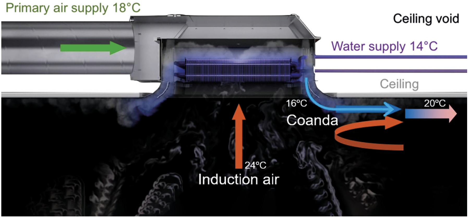
The static pressure consequently reduces below that of the adjacent room air, so drawing in room air through the coil of the chilled beam (possibly via a ceiling void) and through the cool (or warm) coil, to be entrained into the stream of air supplied by the nozzles (as in Figure 2). This induction acts to significantly enhance the velocity of the room air – and so volume flowrate – passing across the coils, so improving the heat transfer to the room air.
The movement of the newly conditioned air across the conditioned space can be reinforced by the Coanda effect to ensure good diffusion distances (or ‘throw’) across the ceiling area. Active ‘chilled’ beams may be used as heating sources when supplied with low-temperature hot water (water temperature typically lower than 50°C to moderate air stratification) in place of cool water, while utilising warm primary air.
The primary air is often used to meet the latent loads in the space (that is, the dehumidification requirement) by having a supply air moisture content set at a level to offset the latent gains in the conditioned space.
To ensure dry cooling, which provides only sensible cooling to the indoor space via the hydronic circuit, the circulating water temperature is maintained above the room air dew point. Mitigating the risk of condensation-inducing humidity spikes in rooms involves employing sensors (such as that shown in Figure 3) on the cold-water supply that might trigger the closure of water valves when moisture levels rise.
Alternatively, continuous monitoring of room relative humidity can prompt thermostat-controlled closure of water valves nearing dew point conditions. Increasingly, condensation protection methods adjust supply water temperature based on room conditions, allowing for continued heat removal while minimising discomfort owing to reduced cooling capacity.
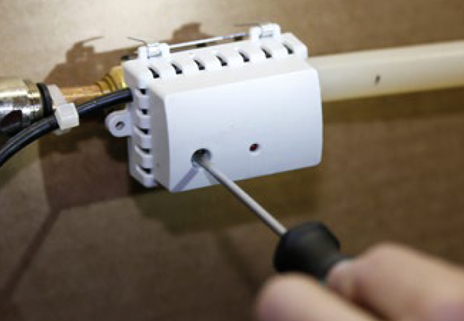
Figure 3: An example of a dew point (dp) temperature sensor that is fixed immediately upstream of the cooling. The dp is internally determined using a temperature-compensated relative humidity (RH) element and a high-accuracy thermistor, which are thermally bonded to the metal plate of the sensor. A volt-free contact relay activates when the dp temperature is below the set point (as set, in this case, using a screwdriver adjustment) (Source: Swegon)
Dry cooling systems rely on having sufficient air supply rates to manage latent loads. For high humidity environments, centralised air handling units (AHUs) must dehumidify outdoor air before distribution – this is often achieved through sorption-treated rotors. As discussed in more detail in REHVA’s chilled beam guide,1 dry cooling offers several system advantages.
As with any hydronic system, moving water as a means of delivering cooling is far more effective than employing air and, in chilled beam applications, the moderately high chilled-water temperatures of 14°C to 18°C provide good opportunities for ambient free cooling. However, the central AHU typically requires chilled water at approximately 6°C to provide dehumidification.
The chiller plant may produce water at 6°C and the required 14°C to 18°C water can be delivered by mixing water from the chiller with return water, which is not an ideal solution; it has a deleterious effect on energy consumption (and system exergy) when compared with a conventional 6°C/12°C distributed chilled-water system, and the higher temperature of water being returned to the chiller plant will reduce its performance (energy efficiency ratio (EER)).
Energy consumption may be reduced if there are dedicated chilled-water production systems for the two different chilled-water temperatures – one for the centralised AHU system and one for the chilled beams. The chillers for the beams can work with a 14°C chilled-water temperature setpoint, which significantly increases their performance, lowers peak cooling demand and reduces the chiller size.
Free cooling can be implemented with, for example, cooling towers (for warmer/drier climates), dry coolers (for colder climates) and geothermal sources (water or ground). However, chilled beam systems will consume more pump energy in comparison with other distributed unit conditioners, as they employ a lower water temperature differential of 2K to 3K, compared with a conventional water temperature differential of 5K to 6K for traditional distributed unit conditioners. Where beams are used for heating, the lower hot-water temperatures of 32°C to 45°C are readily attainable from renewable sources.
Not only is the latent cooling centralised at the AHU, but it also provides driving pressure for room air distribution with central high-efficiency fans as opposed to local, smaller – likely lower efficiency – motor-driven fans that are used in other decentralised room conditioners.
Active chilled beams are engineered to operate without the presence of surface water, and typically eschew filters or drainage systems, so reducing service and maintenance needs –resulting in capital and operational cost savings compared with ‘wet’ systems. In such systems, filters would require periodic cleaning or replacement, and drainage systems demand maintenance to prevent microbial growth.
There are various hybrid beams, including the multi-service chilled beam (MSCB), that also integrate other services into the casing, such as ducts, lighting, cabling, audio equipment and sensors. They can provide an alternative to using additional trunking or possibly alleviate the need for a ceiling service void. They may be fitted directly to the soffit to potentially, for example, offer both a lighting and ventilation solution.
There are also hybrid systems that also incorporate a room-facing cooled surface to provide radiant heat exchange to the room in addition to the conductive heat exchange as the air passes through the coils and across the extended surfaces.
Traditionally, active chilled beams that supply air in constant air volume systems employ fixed geometry air paths that require manual adjustment, such as nozzle replacement, to significantly adjust the primary air flowrate. For a VAV setup, an air flow damper is typically mounted in front of the unit to adjust duct pressure upstream of the active chilled beam.
However, the relationship between duct pressure and airflow is not linear, as it follows a square law relationship so airflow (L.s-1) q = k.√pi where k is the flow coefficient and is related to the geometry of the air path, and pi is the inlet pressure (Pa). When the damper reduces the primary air flowrates, the duct inlet pressure drops and the speed at which the air enters the room is consequently lower.
This will reduce the Coanda effect, so reducing the throw and increasing the likelihood of draughts. The induction ratio is practically constant, with a fixed value of k, so as the primary airflow is reduced, the amount of induced room air is reduced proportionally, as shown in the green line of Figure 4 – hence the heating/cooling capacity available from the water side is significantly reduced at lower primary airflows.
There are also limitations in increasing airflow. Boosting the airflow means increasing the duct pressure; however, the square law relationship can lead to unreasonable duct pressures that can generate increased noise levels. So, although traditional active chilled beams with fixed nozzles can be operated in VAV conditions, it will be within a limited range of primary airflow.
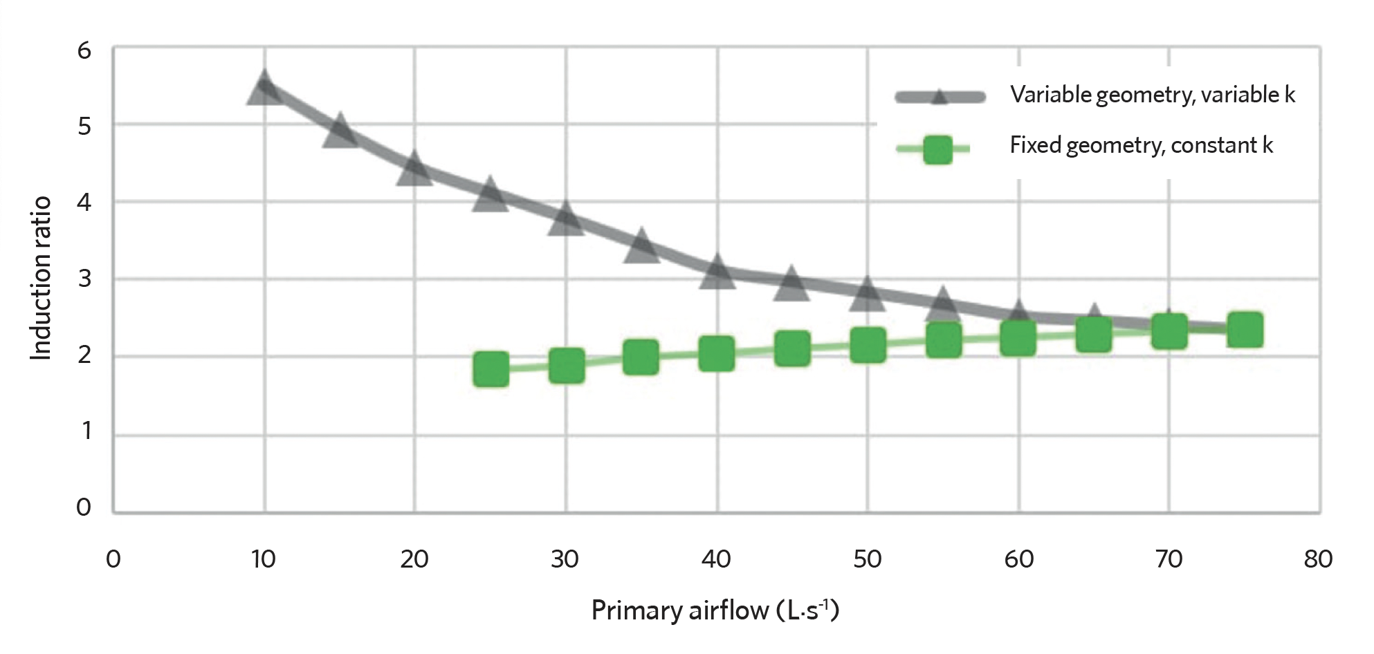
Figure 4: Induction ratio as a function of primary airflow for an example beam with variable geometry compared with fixed geometry outlets (Source: Swegon)
However, active chilled beams are now available where the traditional nozzles are replaced by adaptable geometry ‘slots’ in the supply air plenum. The amount of supply air delivered can then be altered by a controller actuating a change to the slot geometry to alter the value of k. Active chilled beams with variable geometry supplies can operate at different primary airflow rates while the inlet duct pressure remains constant.
As the primary airflow rate is reduced by decreasing the size of the openings in the pressure chamber, k reduces, resulting in an increased induction ratio as shown by the grey line of Figure 4. This enables high induction rates and good cooling/heating capacities even at low primary airflows.
The maintained duct pressure ensures that the speed of the supply air is kept at a level that can maintain the Coanda effect. Conversely, an increase in primary airflows does not require an increase in duct pressure, so a single unit can deliver a wide range of primary airflows.
When there is a need to change the temperature in the room, several parameters may be altered to adjust the amount of cooling/heating delivered to the room. The primary airflow and temperature, as well as the amount and temperature of water flowing through the coil of an active beam, can be adjusted, controlling the amount of heating/cooling delivered to a room.
If it is cold and dry outside, it might be advantageous to increase the airflow when there is a need to increase the amount of cooling. At another point in time, the conditions may be different, and it will be more efficient to increase the flow water rather than to increase the airflow.
Since active chilled beams rely on the induction of room air to generate a flow through the coil, the primary air is always mixed with room air that can be cooled, heated or, when the water valves are closed, unaffected by the coil. So, an active chilled beam might be considered as an induction diffuser, making it possible to operate with lower primary air temperature than required with most diffusers without facing issues with draughts.
A use case for this could be to deliver more cooling via the ventilation air or to reduce the primary airflow rates needed to deliver a moderate amount of cooling, which would make the use of free cooling even more efficient.
In the seemingly only recent independent, comprehensive (and reasonably priced) reference dedicated to chilled beams – the REHVA/ASHRAE Active and Passive Beam Application Design Guide1 – it concludes that ‘compared to alternative HVAC systems, beam systems may offer significant savings in operating costs, namely in energy and maintenance. Replacement costs are also lower. …. The increase in the value of the building associated with the increase in the building useable area should be considered in the TCO (total cost of operation) analysis.’
With the advent of active chilled beams with variable values of k (‘VAV beams’), there may be further opportunities to apply this potentially energy-efficient hybrid solution that, if combined with a well-considered ‘smart’ control strategy, could help optimise the benefits of combined air and water system solutions.
© Tim Dwyer, 2024.
This article was inspired by some recent blogs by Carl-Ola Danielsson of Swegon.
What are the advantages of dry cooling?
Active chilled beams with variable k-factor – an option for both CAV and VAV systems
Our thanks to him for permitting the reuse of parts of his work in the article.
Further reading:
In addition to the REHVA/ASHRAE Active and Passive Beam Application Design Guide, a 2022 paper2 by Latifa et al – Performance evaluation of active chilled beam systems for office buildings – A literature review – provides a good overview of many of the most recent published materials.
References:
1 Woollett, J, and Rimmer, J, Active and Passive Beam Application Design Guide, REHVA/ASHRAE 2016 – .
2 Latifa, H et al, Performance evaluation of active chilled beam systems for office buildings – A literature review, Sustainable Energy Technologies and Assessments issue 52, 2022.