Figure 1
As an efficient technology, thermal energy storage (TES) using phase change material (PCM) can be applied to decrease peak loads, and shift loads, enhance system efficiency, and reduce the size of cooling plants, while maintaining occupant thermal comfort.
In this research, the performance of a latent heat storage unit comprised of organic paraffin PCM enclosed in a finned-tube heat exchanger was evaluated and analysed to determine its viability as a free cooling facility to condition a space during summer in the UK.
While widely used in refrigeration and heat pump systems, finned-tube PCM heat exchangers are seldom applied in TES with PCMs.
A prototype was tested and modelled with computational fluid dynamics (CFD) for the application of night-time cold storage and daytime space cooling during summer. The internal and external design conditions of a typical building were used to determine the type of PCM and the PCM’s operating temperature range required for space cooling.
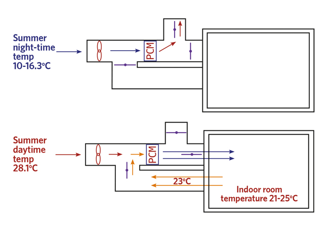
PCM charging is carried out at night. It is not necessary to condition the area at night, so the air will be expelled into the atmosphere
Extensive measurements were conducted on the PCM heat exchanger at different operating conditions and for both PCM charging and discharging processes. To validate the experimental measurements, a 3D CFD model for the PCM heat exchanger was developed and validated.
The combination of the CFD model and experimental investigation determined the performance of the PCM heat exchanger at various operating and design conditions.
Phase change materials
PCMs can be classified as organic, inorganic, or eutectic. Organic PCMs, such as paraffins, have the advantages of being non-toxic, non-corrosive, and chemically stabilised materials at low temperatures1.
The melting points of paraffins range from -30°C to 120°C2. They have a high latent heat of fusion, but drawbacks include a lower thermal conductivity of about 0.2W·m-1·K-1, low density, and less stability at high temperatures3. Inorganic materials mainly consist of salt hydrates, metallics, and their mixtures, and they cover a wide temperature range similar to that of organic PCMs.
Experimental investigation
Test rig setup and measurements

The experiment was conducted with an air conditioning laboratory unit that had been modified to contain a PCM finned-tube heat exchanger. The heat exchanger was enclosed in a 250x250mm extension duct that was bolted to the outlet of the air conditioning rig.
To facilitate the energy charge or discharge of the PCM heat exchanger, up to four 1kW electric heaters and a refrigerant cooling coil modulated and controlled the incoming airflow parameters to the PCM heat exchanger.
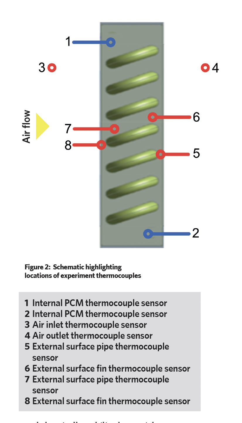
The airflow parameters of temperature and humidity at the heat exchanger inlet and outlet were measured using dry and wet bulb thermometers (Figure 2). To ensure accurate measurement of airflow velocity for the PCM heat exchanger, it was determined that only the minimum and maximum fan speeds would be set and applied.
PCM temperature and material selection
The PCM selected was an organic hydrocarbon PlusIce A17. CIBSE Guide A was consulted to determine the most common summer internal thermal comfort range, which is between 21˚C and 25˚C in the UK.
The frequency of occurrence method was used to determine the external daytime summer conditions. The dry and wet bulb temperatures of 28.1°C and 19.2°C were chosen using a frequency of occurrence of 0.4 %. London was selected as the extreme outlier.
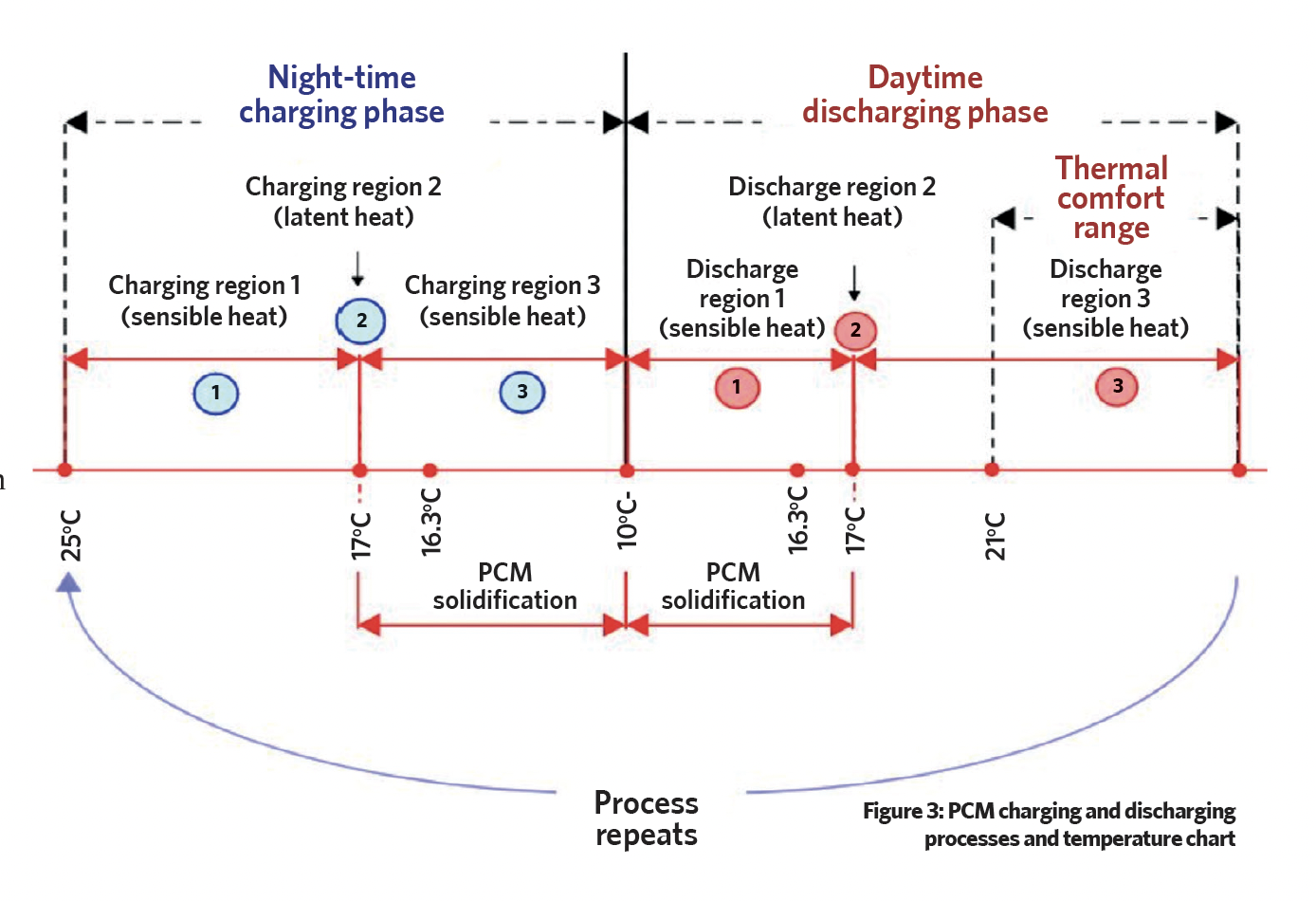
CIBSE Guide J was used to estimate the temperature range for PCM charging during the summer night-time. Between the hours of 19:00 and 06:00 in July, the average overnight temperature was measured. This implies that the solidification/melting temperature of PCM must be higher than 16.3°C. A 2-5K subcooling is acknowledged to be required to ensure adequate PCM solidification.
PCM charging and discharge processes
At night, when ambient temperatures are lower, an inlet fan forces 10-16.3°C airflow to pass through a duct containing a PCM heat exchanger.
The cold air travels across the heat exchanger, cooling the PCM material, which changes the PCM phase from liquid to solid. This procedure, namely PCM charging, is carried out at night. Because it is not necessary to condition the area at night, the air will be expelled into the atmosphere.
The summer daytime outdoor temperature is 28.1°C. Recirculation will be used to cool down the air flowing to the PCM heat exchanger, ensuring the PCM cooling lasts longer and the PCM selection is closer to, and lower than, the internal thermal comfort range.

The 28.1°C outdoor air is mixed with the 23°C return air. This makes the mixing airflow temperature 23.51°C. The PCM heat exchanger cools incoming airflow, lowering its temperature. Latent heat is transferred as the PCM changes phase to liquid.
The experimental design was intended to replicate the above-mentioned conditions. Figure 1 visually presents the charging and discharging processes. Figure 3 depicts the PlusIce PCM A17 discharge and charging phase processes using the external temperature expected in the UK during the summer. Region 2 is represented by latent energy storage/release occurring at a phase change temperature of 17°C.
Mathematical and numerical methodology
3D CFD model and validation

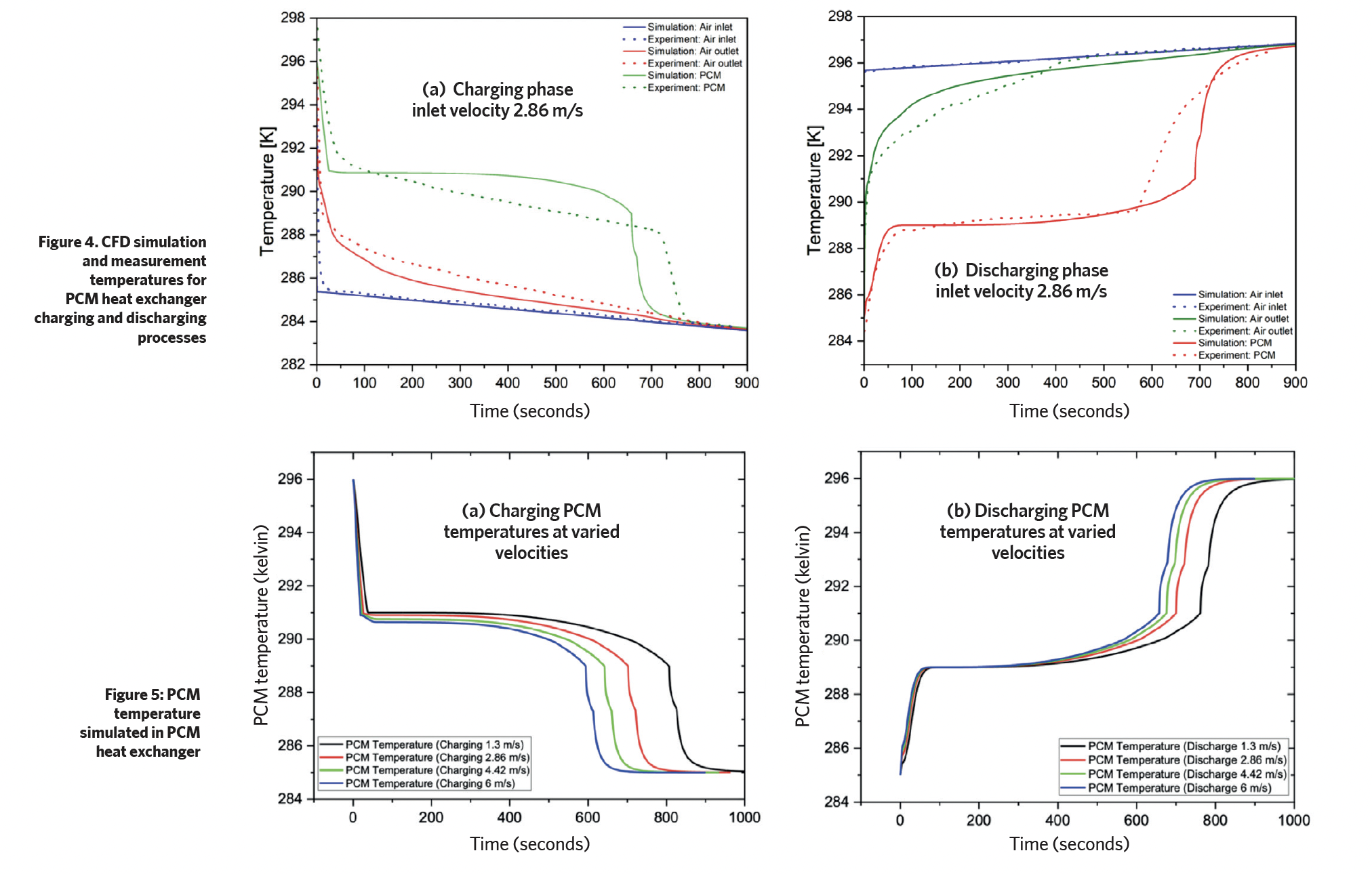
A 3D CFD model using the Ansys Fluent software was developed. Figure 4a shows the temperature that was taken from the CFD simulation and the experimental results for the charging process at four different airflow velocities. The average discrepancy was about 6% between the experiment and the CFD simulation.
Figure 4b depicts discharging Ansys simulations and thermocouple temperature measurements at the same set of velocities. The results obtained from the experimental data and the CFD simulation were reasonably consistent.
Temperature contours demonstrate that the majority of rapid heat transfer happens between 1 and 300 seconds. After this amount of time, the inlet and outlet airflow temperatures are comparable, but not at a steady state.
To quantify when airflow velocity varies from 1.3 m/s to 6 m/s, the dynamic variations of PCM temperatures with time for both PCM charging and discharging processes are simulated and shown in Figure 5(a) and Figure 5(b) respectively.
Experimental investigations were carried out at design operating conditions of night-time PCM charging and daytime PCM discharging processes. A 3D CFD model for the PCM heat exchanger was developed and validated by comparing it with the respective measurement results.
The validated CFD model evaluates and compares the PCM heat exchanger performance at different design and operating conditions.
Based on the simulation results, for either the PCM charging or discharging process, the PCM undergoes sensible heat, phase change, and sensible heat stages.
It verifies that significant cold energy can be stored or released in the PCM with a two-phase state. The phase change periods, however, are affected greatly by some important operating parameters, such as external heat transfer fluid (airflow) flow velocity.
When the airflow velocity increases from 1.3m/s to 6m/s, the phase change periods decrease by 25% and 23% for PCM charging and discharging processes.
References:
- V Butala and U Stritih, Experimental investigation of PCM cold storage, Energy and Buildings, vol 41, no 3, pp354–359, 2009.
- R Baetens, B P Jelle and A Gustavsen, Phase change materials for building applications: a state-of-the-art review, Energy and Buildings, vol 42, pp1361-1368, 2010.
- G Fang, S Wu and X Liu, Experimental study on cool storage air conditioning system with spherical capsules packed bed, Energy and Buildings, vol 42, pp1056-1062, 2011.
The paper was presented at the 2023 Technical Symposium. The 2024 event is on 11-12 April www.cibse.org/symposium
Professor Yunting Ge is director of the Centre for Civil and Building Services Engineering at LSBU. Co-authors were Arton Merovici, research associate, and Dr Xinyu Zhang, postdoctoral research associate, both at LSBU
