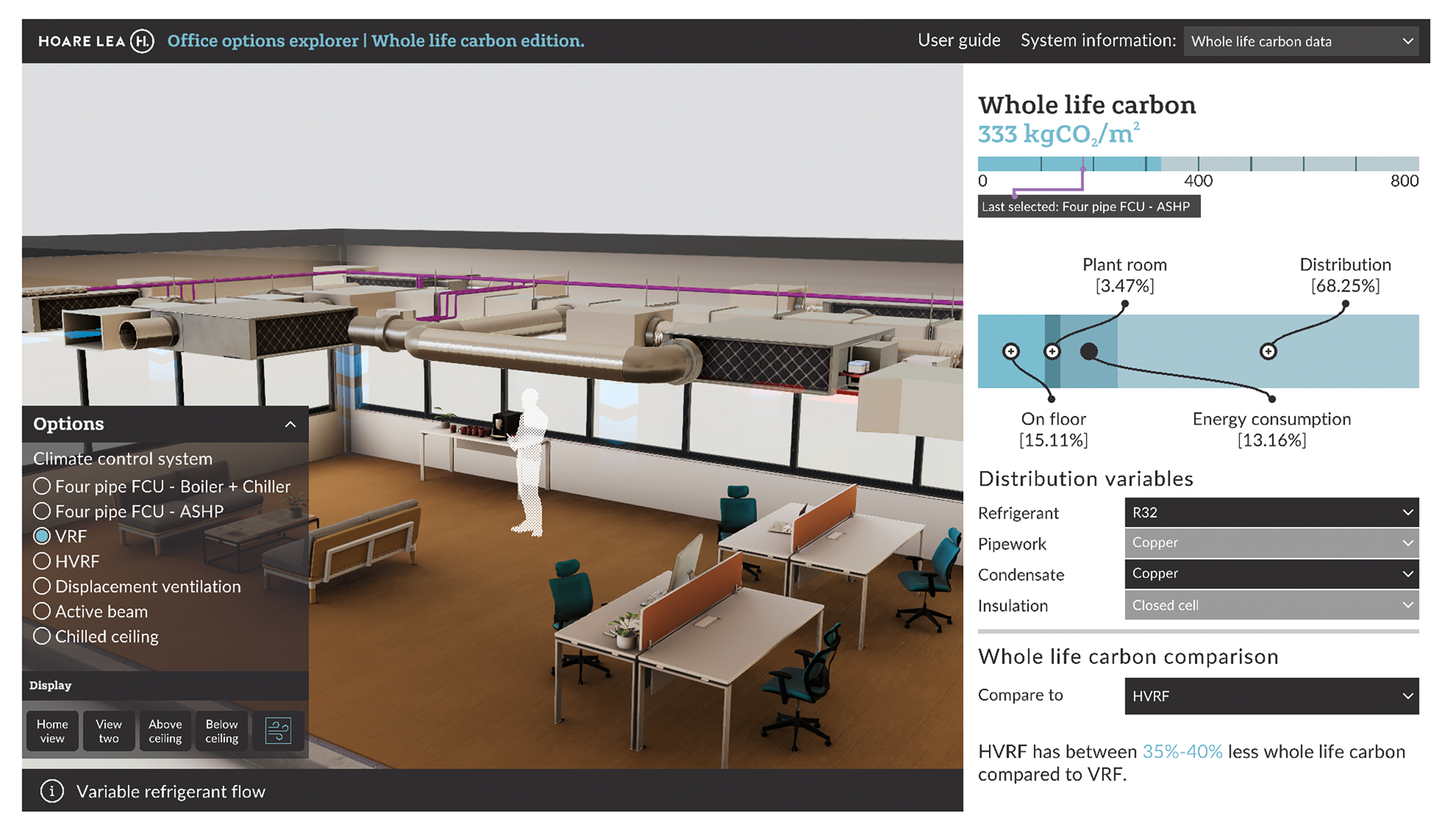
Visualisation of VRF option for an office
Heating, ventilation and air conditioning (HVAC) systems are crucial for indoor comfort, but are also significant contributors to a building’s carbon footprint. The growing emphasis on sustainability in building design has highlighted the need for comprehensive whole life carbon (WLC) analysis in HVAC systems.
The drive towards net zero carbon buildings necessitates innovative tools that can assess and visualise the WLC impact of various HVAC systems. This article presents a 3D visualisation tool based on a framework for early-stage selection of HVAC systems, focusing on minimising embodied and operational carbon emissions. The tool aims to support decision-making in the early stages of building design, aligning with net zero carbon goals.
Users can evaluate multiple systems across various criteria, taking into account different material selections
The concept of whole life carbon includes all greenhouse gas (GHG) emissions throughout the entire life-cycle of a building, covering operational and embodied carbon emissions. Embodied carbon emissions pertain to GHG emissions resulting from the manufacture, transportation, maintenance, and disposal of buildings, while operational carbon emissions indicate GHG emissions associated with the day-to-day operation of a building. CIBSE TM65 documents embodied carbon emissions for MEP systems and has a standardised methodology for assessing embodied carbon for products that are lacking Environmental Product Declarations.
The relationship between embodied carbon and operational carbon will evolve significantly as demand-side electrification progresses. This change is expected because of anticipated improvements in power generation efficiency, driven by a greater reliance on renewable sources, which should reduce the carbon emissions associated with electricity generation. Additionally, European Union regulations and standards intend to phase out the use of refrigerants with high global warming potential (GWP).
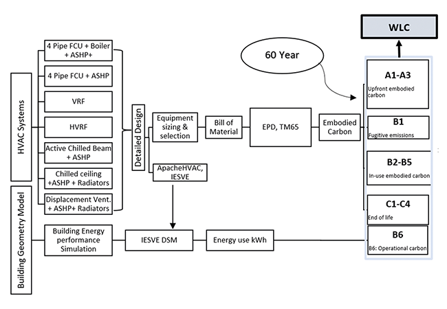
Figure 1: Methodology for calculating whole life carbon
In the early design stages, HVAC engineers face the challenge of limited data, particularly regarding the carbon footprint of HVAC equipment and materials. Making informed decisions at this stage can influence a building’s long-term environmental impact significantly.
The rapid pace of technological advancements further complicates the selection process, making it essential to integrate innovative benchmarking solutions and interdisciplinary collaboration. Figure 1 shows the framework used to incorporate data for the visualisation tool.
Comparative analysis of HVAC systems via visualisation
The digital visualisation tool incorporates several essential features to address the challenges of whole life carbon analysis in HVAC systems. First, it integrates normalised data on embodied and operational carbon emissions, offering a comprehensive view of each HVAC system’s whole life carbon impact. This data is sourced from standardised databases and industry benchmarks, to ensure its accuracy and reliability.
Second, the tool includes interactive HVAC systems’ performance, energy consumption and WLC comparison, and visualisation of the system in 3D, using different material selections.
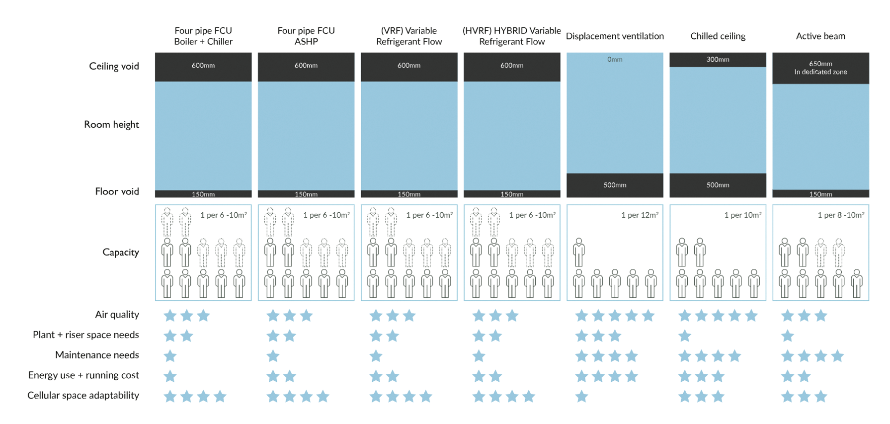
Figure 2: Sample showing whole life carbon calculated for seven system
These schematics allow users to engage with visual representations of system components and their associated carbon impacts, aiding in understanding the consequences of various design choices.
Third, the tool’s comparative analysis capability enables users to evaluate multiple HVAC systems across various criteria, taking into account different material selections for major components that may provide variations in embodied carbon for the selected system. This feature is particularly valuable for making informed decisions aimed at achieving net zero carbon goals.
Finally, the tool is designed with a user-friendly interface. It guides users through complex datasets and offers clear visualisations, making the information accessible to both technical and non-technical users.
The visualisation tool in Figure 2 show seven climate-control systems offering different material options and configurations. See panel for an outline of each.
Summary of system options
4-pipe FCU systems: Available with boiler and chiller, or ASHP, these systems use low-temperature hot water (LTHW) and chilled water pipes, along with fan coil units and fresh air handling systems, to manage ventilation and maintain comfort
Variable refrigerant flow (VRF) systems: These employ refrigerant pipes and branch controllers for precise temperature regulation. Some VRF setups also integrate a hybrid of water and refrigerant components, known as hybrid VRF systems (HVRF).
Active chilled beam system with ASHP: This system uses chilled beams and fresh air handling units to provide comfort throughout the building. All zones receive either cold water or hot water via 4-pipe units, allowing some zones to receive cold water for space cooling while others simultaneously receive hot water for space heating. The units contain an integral air supply that passes through nozzles, inducing air from the space, up through the recessed ceiling units.
Chilled ceiling and radiator system with ASHP: This system provides heating and cooling for the entire building. LTHW and chilled water (CHW) pipework are distributed from the plantroom to each floor and then further conveyed at a high level on each floor plate. The LTHW pipes connect to low-temperature heating radiators, while the CHW pipes are linked to passive-chilled ceilings. The system relies on natural convection within the conditioned space.
Displacement ventilation and ASHPs: These systems provide heating for the entire building. LTHW pipework is distributed from the plantroom to each floor and then further distributed within each floor. The LTHW pipes are connected to low-temperature heating radiators, and the system relies on displacement ventilation.
Each system’s design flexibility allows for tailored solutions that can be adapted to specific building needs and material preferences. The digital tool provides a breakdown of comparisons between these systems.
It is worth noting that, while the visualisation tool provides comparisons on operational energy and whole life carbon breakdown, it also offers hints and guidance on associated parameters, such as air quality and thermal comfort potential.
Results
According to the tool, the gas boiler baseline scenario has the highest energy consumption, at approximately 60kWh·m-2.
When comparing electrical-based systems using vapour compression, the air source heat pump-fan coil unit (ASHP-FCU) exhibits the highest energy consumption, at 44kWh·m-2, while the ASHP radiator system coupled with displacement ventilation has the lowest, at around 18kWh·m-2. This represents a reduction of about 60% in energy consumption compared with the ASHP-FCU system.
The active chilled beam system and passive ceiling systems also demonstrate significant advantages over variable refrigerant flow (VRF) and hybrid VRF (HVRF) systems.
In the context of embodied carbon, systems that incorporate ASHPs, such as the ASHP radiator system with displacement ventilation, demonstrate the lowest operational and embodied carbon emissions.
These findings underscore the importance of selecting HVAC systems that balance efficiency with low carbon emissions, especially in the context of refrigerant GWP and associated leakage percentages.
Although most VRF systems use R410a, it is intended in this sample to compare the potential of VRF with low-GWP refrigerants, such as R32. However, a few smaller VRF systems are introduced with R32, which has a lower GWP of 675kgCO2e/kg but comes with limited capacities.
When using R32 refrigerant, additional precautions must be considered during the planning and installation of VRF systems because of its classification as ‘mildly flammable’.
Figure 3 depicts the embodied carbon associated with all system components and materials, inclusive of operational energy emissions and refrigerant leakage emissions throughout their lifespan.
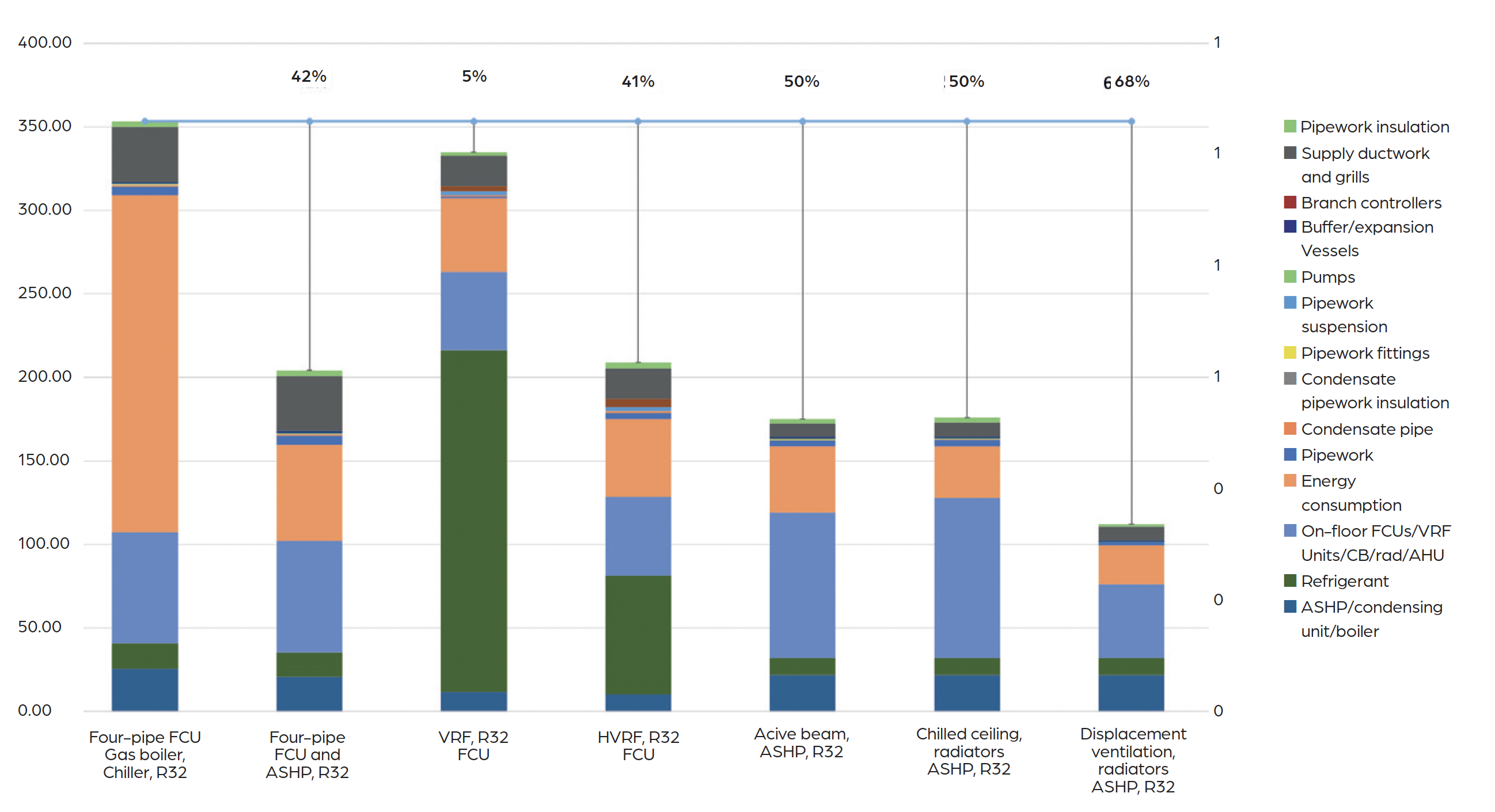
Figure 3: Whole life carbon breakdown per HVAC system, kgCO2e.m-²
The baseline gas-boiler scenario has the highest WLC, at 353kgCO2.m-2; however, the VRF system is nearly comparable, at 335kgCO2.m-2. This is noteworthy given the use of a lower-GWP refrigerant.
If R410a is used in line with major market installations and commercially available systems, the VRF WLC will surpass the baseline scenario. The ASHP radiator system coupled with displacement ventilation exhibits the lowest WLC, at 112kgCO2e.m-2, representing a reduction of approximately 45% in WLC compared with the ASHP-FCU, at 204kgCO2.m-2.
The active chilled beam system and passive ceiling systems demonstrate comparable WLC values at 175kgCO2.m-2, showcasing a 15% reduction compared with ASHP-FCU and HVRF systems, and a 47% reduction compared with the
VRF system.
Selecting the appropriate HVAC system within the context of WLC requires a comprehensive approach that considers embodied and operational carbon.
The rise of artificial intelligence has led to the development of advanced HVAC digital visualisation tools that are now crucial for HVAC engineers and building designers. These tools enable more sustainable decisions on climate-control systems during the early stages of building design.
By incorporating low-GWP refrigerants, efficient design strategies and advanced materials, the carbon footprint of buildings can be reduced significantly. As the industry moves towards stricter carbon-reduction targets, such holistic approaches will be essential for achieving net zero goals.
About the author
Dr Esam Elsarrag MCIBSE is a consultant at Hoare Lea
